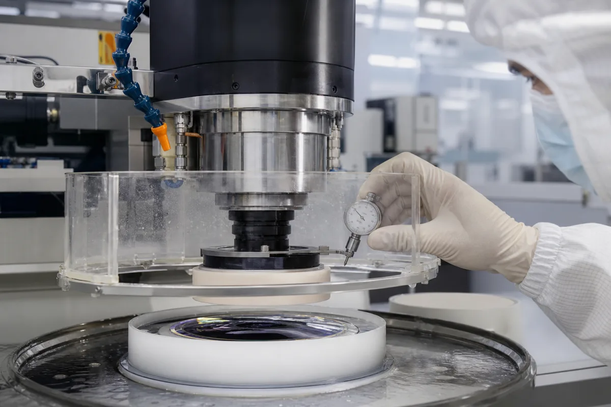
Polishing spindle assembly for optics: the work spindle that turns the lens and the tool spindle that drives the pad or bonnet, compared by speed, power, chucking and runout
Work and tool spindles on optical polishing machines · 1–1,500 rpm at 1.3–1.8 kW, 25–2,000 rpm at 5 kW, bonnet tool spindles to 3,000 rpm, hydraulic expansion chucks of 12, 25 and 40 mm, work spindle runout under 5 µm radial and 10 µm axial
A polishing machine for optics has at least two spindles: a lower work spindle that holds and rotates the blocked lens, and an upper tool spindle that drives the polishing pad, pitch tool or inflated bonnet against it. The spindle assembly decides what the machine can hold, how fast and with how much torque it turns, how the tool and part are clamped, and how true they run. When a spindle is bought as a replacement, specified for a new machine or checked after a crash, these are the figures to compare and the checks to repeat.
Work-holding and tool-driving spindle assemblies of polishing machines for optical lenses, domes, mirrors and freeform optics: spindle speed range and motor power, drive and encoder, workpiece weight and inertia, hydraulic expansion and pneumatic bladder chucks, vacuum work holding, cooling, load-cell probing, truing spindles, and radial and axial runout with the dial-indicator checks used to verify them. The complete polishing machines, their machine types and lens ranges are covered on the Precision optical lens polishing machine page; bell-clamp centring and edging on the Precision optical lens centering machine page; the pneumatic loading and contact-force control that presses the tool onto the lens on the Polishing-pressure control mechanism for optical lens polishing page; double-side planetary machines for disk substrates on the Hard drive platter polishing machine page. Metal-cutting motor spindles for machining centres, grinders and lathes are covered on the High-speed spindle, Built-in motor rotary spindle for CNC lathes and Spindle assembly pages and are outside this page.
CNFX editorial research · Sources checked October 13, 2026 · 4 sources
Work spindle and tool spindle: 1–3,000 rpm, 1.3–5 kW and what each chuck holds
Two published spindle sets show how the assembly scales with part size. OptiPro's high-speed spherical polishers pair a lower work spindle with an upper tool spindle of the same speed and power, both fitted with a hydro-expansion chuck, and use a pneumatic bladder as the work chuck. [1] Zeeko's IRP machines split the job differently: a tool spindle (H axis) carried on two rotary axes that swing it about a virtual pivot for precessed bonnet polishing, and a work spindle (C axis) on the linear axes. [2]
On the PRO 160P+ the lower position carries two spindles of identical specification, a work spindle and a truing spindle, so the polishing tool can be trued in the program after each cycle without being changed. [1] Zeeko cools both the tool and work spindles from an external chiller, and builds a 125 N load cell into the tool spindle so the machine can probe the part and reference itself. [2]
Editorial calculation: at constant power, torque scales with power over speed; 5 kW at 2,000 rpm is about 24 N·m, against about 8.3 N·m for 1.3 kW at 1,500 rpm, a ratio of roughly 2.9 between the ePX 200 and PRO 80P spindles at their top speeds.
Ø40 mm hydraulic chuck for the work; Ø25 mm for the tool [3]
Ask for both spindles separately: speed range, continuous power or torque, encoder, maximum workpiece or tool mass and inertia, chuck type and bore, cooling, and whether a vacuum or truing spindle is available.
02
Under 5 µm radial, under 10 µm axial and the 15 µm virtual-pivot clock check
Zeeko's specification gives runout for the work spindle rather than a general figure for the machine: under 5 µm radial and under 10 µm axial on the C axis of both the IRP200 and the IRP400. [2][3] For the tool spindle it specifies instead how far a setting ball clamped in the H-axis chuck strays as it rotates about the virtual pivot, under 40 µm, because a precessing bonnet must stay centred on that pivot. [2]
The pivot is set at the factory and is meant to need resetting only after a collision. To check it, the IRP100 maintenance manual clamps the setting tool in the tool spindle, places a dial indicator on the centre line of the X and Y axes with its magnetic base beside the work spindle, and accepts 15 µm or less of variation while the B axis turns through +90° and −45° and the A axis through ±120°; resetting is left to Zeeko personnel. [4] The same manual has the grub screws of both hydraulic chucks removed, cleaned and re-greased weekly. [4]
The swing axes that carry the tool spindle are geared, not direct: TwinSpin 140 and 80 reducers driven by servo motors, turning at up to 25 rpm, with ±1 arcmin repeatability at the motor. [2] Editorial calculation: the 15 µm accepted in the IRP100 field check is about 0.38 of the under-40 µm setting-ball figure in the IRP200 specification; the two documents cover different models and differently defined tests, so ask the supplier which value applies to the spindle you buy.
Ask how radial and axial runout are measured (at the chuck face, on a test bar or on a setting ball), at what speed, and what the acceptance value is after a spindle exchange or a crash.
03
Data for an optical polishing spindle
Paste it into your enquiry below or into an email to a maker, then replace every bracket.
Machine: [polisher make and model; spindle position (work, tool, truing)]
Parts: [diameter range; mass; radius or freeform]
Speed and power: [rpm range; kW or N·m]
Clamping: [hydraulic expansion bore; bladder or vacuum; arbor]
Runout: [radial and axial limit; how measured]
Drive and feedback: [direct or belt; encoder]
Services: [chiller; air; slurry sealing]
Tool spindle extras: [load cell; bonnet pressure supply; pivot accuracy]
Explore company information and manufacturing capabilities, then discuss the scope of your project with a relevant supplier.
Share this page
Compiled and source-reviewed by the CNFX editorial team.
Each manufacturer above links to the page on that company's own website where the product is listed, with the date we checked it. How we source and review
· Page last updated 13 October 2026
Buyer questions
How fast do optical polishing spindles turn?
OptiPro lists 1–1,500 rpm work spindles at 1.3 or 1.8 kW and 25–2,000 rpm at 5 kW; Zeeko's bonnet tool spindle on the IRP200 runs at 10–3,000 rpm and its work spindle at 0–1,000 rpm. [1][2]
What runout does a polishing work spindle hold?
Zeeko specifies under 5 µm radial and under 10 µm axial runout for the work spindle of its IRP200 and IRP400. [2][3]
How is a bonnet polishing spindle checked after a collision?
Zeeko's IRP100 manual clamps a setting tool in the tool spindle and accepts up to 15 µm on a dial indicator while the swing axes rotate. [4]
What chucks hold the lens and the tool?
OptiPro fits hydro-expansion chucks on both spindles with a pneumatic bladder work chuck; Zeeko uses hydraulic chucks of 12, 25 or 40 mm and optional vacuum. [1][2][3]
Sources and what still needs a direct check
Sources checked 2026-10-13. Specification sheets from two polishing machine builders, OptiPro Systems (USA) and Zeeko (UK), and Zeeko's maintenance manual, which describes the dial-indicator check of the tool spindle pivot.