Power inductors · Saturation current against heating current, core material and saturation shape, temperature at high ambient, SRF
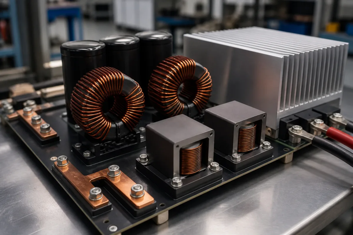
A power inductor stores energy in a magnetic field to smooth current in DC-DC converters, power factor correction stages and filters; on power boards like the one pictured it may be a toroid on a powder core or a gapped ferrite E- or U-core winding, and on smaller boards a surface-mount part. Ask three things first: which current limit (saturation or heating) governs the part at your peak and rms current, how the core material saturates and behaves with temperature, and what temperature the part will reach at your ambient.
Power inductors and chokes for switching converters and power stages, including surface-mount, toroidal and gapped-core types. Common-mode chokes, transformers, RF chip inductors and line reactors are outside this page.
CNFX editorial research · Sources checked October 12, 2026 · 4 sources
Coilcraft's application note on current and temperature ratings defines saturation current (Isat) as the current at which inductance drops a specified percentage below its value with no DC current, caused by core saturation, and Irms as the direct current that raises the part's temperature a specific amount above 25 °C ambient through I²R losses. Coilcraft writes: “The limit is typically a 15°C rise for chip inductors and a 40°C rise for power inductors”, measured on top of the part in still air with no heat sinking. [1]
The same note says that for some inductors Isat is lower than Irms, so the core saturates first, while “For many inductors, Isat is higher than Irms”; it may publish only the limiting one, or both. It warns that “ESR from inductor manufacturers is typically measured on an impedance analyzer at very low (all AC) current with no DC bias current”, so I²R estimates and SPICE models should not be used for loss or efficiency analysis unless the ESR is confirmed at the application current. [1]
Editorial note: compare Isat with the peak current (DC plus half the ripple) and Irms with the rms current, and check which inductance drop the datasheet's Isat is defined at, since the percentage is stated by each maker. Editorial calculation: with a 5 mΩ DC resistance, 10 A rms dissipates about 10² × 0.005 = 0.5 W in the winding alone, before any core loss; the resistance is an assumed example.
Give the supplier the converter topology, input and output voltage, switching frequency, required inductance at full load, DC and peak current, ripple current, ambient temperature, cooling, footprint and height limits, and whether a shielded part is needed.
02
Choose the core material by how it saturates
Magnetics, a core maker, explains that power inductors need an air gap to store energy and avoid saturation, either as a discrete gap (Magnetics: “Discrete gaps are most commonly used in ferrite cores”) or distributed through a powder core. Gapped ferrite has low AC core loss at high frequency but low saturation flux density that falls significantly with temperature, and reaches a sharp saturation point that needs a lot of headroom; discrete gaps also bring fringing losses in the coil and EMI. Commercially useful soft magnetic materials range from about 0.3 T to 1.8 T saturation flux density. [2]
Powder cores saturate gradually and keep a useful, predictable inductance as current rises; Magnetics lists operating well into the curve (80% to 50% of initial permeability) as a way to a smaller part, with little shift over temperature and natural fault tolerance. Among powder materials it describes MPP as second-lowest in core loss but costliest, High Flux best for inductance under heavy DC bias, Kool Mμ as a lower-cost option, and iron powder lowest in cost but higher in loss, with an organic binder that can age at high temperature. [2]
In its large DC inductor example, a 60-permeability High Flux core kept about 83% of its initial permeability at 56.5 oersteds of DC magnetising force, which it calls a safe operating point; magnetising force is found from H = 0.4π × turns × current ÷ magnetic path length (cm). [2]
03
Ask how a molded inductor's powder core was made
Researchers at National Cheng Kung University made molded power inductor cores by uniaxially pressing amorphous FeSiCrB alloy powder, carbonyl iron powder and a high-temperature silicone resin, and compared heat treatment of the powder before pressing with heat treatment of the pressed body at 500 °C. They state that molded inductor power loss comprises hysteresis loss, which dominates at low frequency, and eddy-current loss, which rises rapidly with frequency, and that the inductor must keep its inductance under DC bias. [4]
The authors attribute the gain to small carbonyl iron particles filling gaps between the larger amorphous particles, raising compaction density, and to post-pressing heat treatment relieving pressing strain and crystallising nanocrystalline α-Fe, which lowers coercivity and hysteresis loss. [4]
Editorial calculation: cutting 2 MHz core loss from 580 kW/m³ to 300–400 kW/m³ is a 31–48% reduction; for a core volume of 0.1 cm³ (1 × 10⁻⁷ m³, an assumed size), 580 kW/m³ corresponds to 58 mW of core loss and 300 kW/m³ to 30 mW at the authors' test condition. Ask the supplier for the core material, its heat treatment and the core loss at your switching frequency and ripple, alongside the Isat and Irms definitions above. [4][1]
NCKU measurement
Value
Saturation magnetization of FeSiCrB powder, untreated / heat-treated
LCR meter with magnetic fixture 1 MHz–1 GHz; B-H analyzer for loss; DC-bias superposition at 1 MHz [4]
04
Estimate temperature at high ambient and check SRF
Coilcraft's note shows how to estimate the component temperature when rated current flows at an ambient above 25 °C: Tc = Ta + Tr × (1 + α × (Ta − 25)), where Tr is the datasheet temperature rise and α ≈ 0.00385 for copper, because wire resistance and therefore I²R loss rise with ambient temperature. [1]
Editorial calculation: a power inductor rated for a 40 °C rise, run at full rated current in an 85 °C ambient, reaches about 85 + 40 × (1 + 0.00385 × 60) ≈ 134 °C. The note's simplified numeric form gives about 133 °C; either way the part must be rated for that temperature. [1]
Coilcraft's note on self-resonant frequency (SRF) explains that above the first resonance with its own capacitance an inductor stops behaving as an inductor, and that measured SRF depends on the test instrument and fixture; it specifies SRF for its power inductors as typical, since fixture effects are negligible at higher inductance values. [3]
05
Compare what suppliers offer
Suppliers linked to this page list power inductors; each card links to the page reviewed.
Listings include shielded and unshielded SMD power inductors, molded and flat-wire inductors, drum-core and CD-type inductors, toroidal power inductors, high-current inductors and PFC inductors, alongside common-mode chokes and transformers. Ask each supplier how it defines Isat and Irms, the core material, and the measured inductance-versus-current and temperature-rise curves.
06
Trace the inductor parts
This is a functional reference built from the sources cited; it is not one maker's specification.
Fill the specification fields with values for your converter
A power inductor quotation needs values for your converter. The table explains each field, gives published values where a reviewed source states them, and says what to obtain from the supplier.
Ferrite flux capacity falls with heat; powder stays stable. [2]
Curve over temperature.
Weight (g)
Board mass.
Weight.
08
Send the converter and thermal data together
Paste it into your enquiry below or into an email to a maker, then replace every bracket.
Converter: [topology; Vin; Vout; frequency]
Inductor: [L at full load; DC current; peak current; ripple]
Thermal: [ambient; cooling; maximum part temperature]
Size: [footprint; height; shielding]
Core: [preferred material if any]
Data: [L vs I curve; temperature rise curve; loss data]
Explore company information and manufacturing capabilities, then discuss the scope of your project with a relevant supplier.
Share this page
Compiled and source-reviewed by the CNFX editorial team.
Published product pages show what a company offers, not tested performance. Confirm the legal seller, factory and scope for your order. How we source and review
· Page last updated 13 October 2026
Buyer questions
What is the difference between Isat and Irms?
Coilcraft defines Isat by a stated drop in inductance from core saturation and Irms by a set temperature rise from I²R losses, for its power inductors a 40 °C rise. [1]
Do ferrite and powder cores saturate the same way?
No. Magnetics notes gapped ferrite saturates sharply and loses flux capacity with temperature, while powder cores roll off gradually. [2]
How hot will an inductor run at 85 °C ambient?
Using Coilcraft's equation, a part rated for a 40 °C rise at full current reaches about 134 °C (editorial calculation). [1]
What sets core loss in a molded power inductor?
A National Cheng Kung University study found that adding 30–70% carbonyl iron powder to amorphous FeSiCrB powder cut power loss at 2 MHz from 580 kW/m³ to 300–400 kW/m³, and heat treatment after pressing raised permeability. [4]
Sources and what still needs a direct check
Sources checked 2026-10-12. Coilcraft is an inductor maker; its notes describe its own rating methods. Magnetics is a magnetic core maker comparing its powder cores with ferrite. A National Cheng Kung University study reports measured core properties of molded inductor powder mixes.