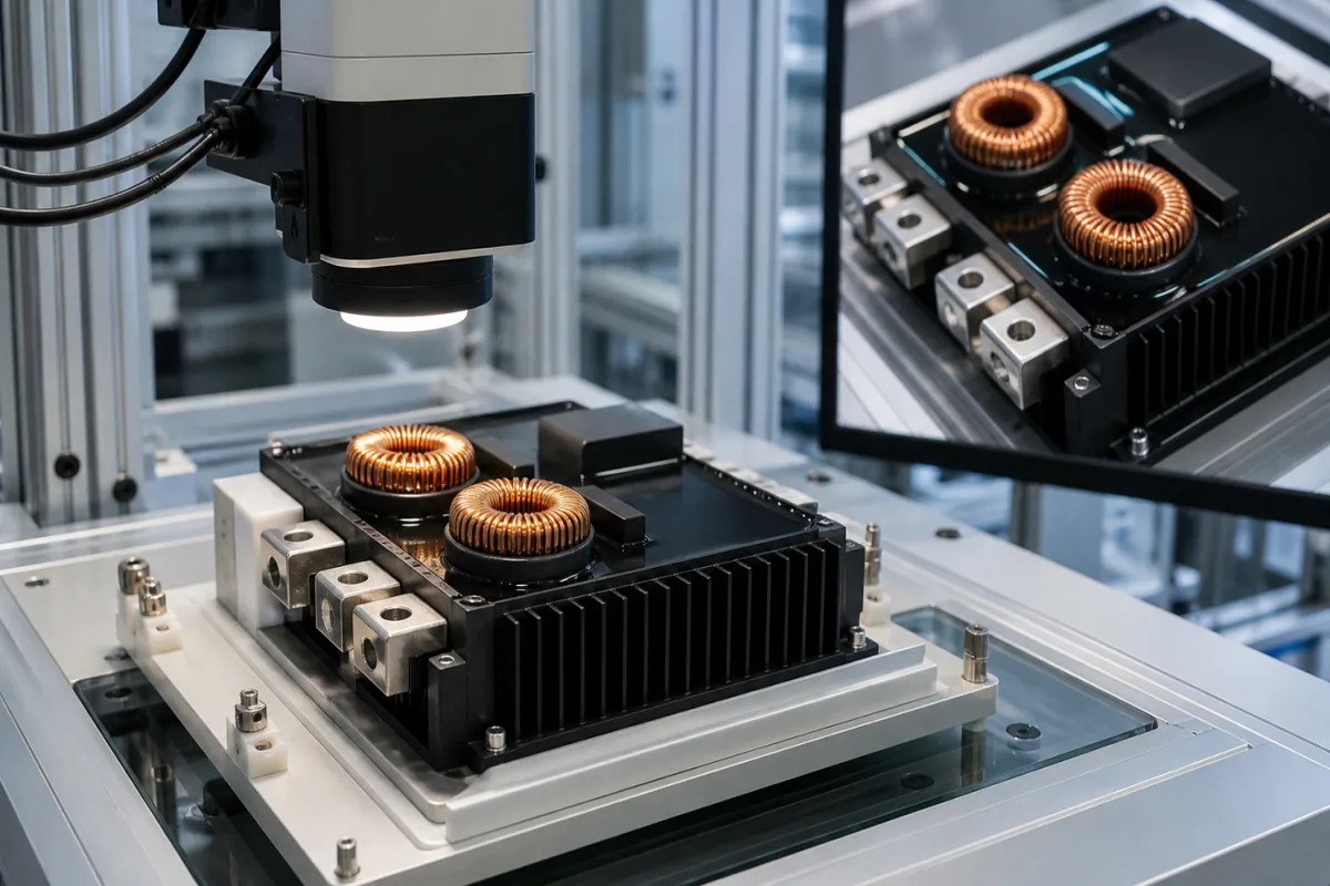
Power management circuit of a Class-D audio amplifier module: housekeeping rails, power-up sequencing and bus-voltage protection
Class-D audio amplifier modules · housekeeping rails taken from the main bus, startup and shutdown sequencing, bus under- and over-voltage trips, half-bridge bus pumping
A Class-D amplifier board takes its power from a high-voltage bus, either a symmetric ±B pair or a single PVDD rail, but its gate drivers, preamplifier and logic need low-voltage rails of their own. The power management circuit derives those rails, controls the order in which the stages start and stop so that the speaker hears no click, and trips the output stage if the bus falls too low or rises too high. Three things decide the design: which bus arrangement the board accepts and which rails it makes on board, how start-up and shutdown are sequenced, and what bus-voltage limits and fault behaviour it has, including the over-voltage a half-bridge can pump back into its own supply.
The supply-side circuitry on Class-D audio amplifier boards and modules: housekeeping regulators for gate-drive, analog and logic rails, start-up and shutdown sequencing and muting, bus under-voltage and over-voltage protection, speaker DC protection signalling to the supply, bus capacitors and bus pumping in half-bridge stages. Amplifier power ratings, distortion and cooling are covered on the Audio amplifier module page; linear amplifiers with toroidal-transformer supplies on the Linear (class AB) amplifier module page. Packaged DC-DC converter modules are covered on the DC-DC converter page; multi-rail power management ICs on the Power management IC (PMIC) page; AC-DC supplies that feed equipment on the Power supply module page; EV on-board chargers on the Power electronics module for electric vehicles page; inverter power-stage boards on the Power electronics board page; wind turbine converter cabinets on the Power converter for a wind turbine page; the 3.3 V regulator of a radio module on the Power regulator for a Wi-Fi module supply rail page; audio DSP boards on the Digital audio signal processor module page.
CNFX editorial research · Sources checked October 13, 2026 · 3 sources
From one bus to gate-drive, analog and logic rails, and the order they come up in
Two reference designs show the two bus arrangements. Infineon's IRAUDAMP4A, a two-channel half-bridge board, needs only a symmetric pair of supplies of ±25 V to ±35 V and makes its housekeeping rails on board: ±5 V for analog signal processing such as the preamplifier, and a +12 V VCC referenced to −B for the Class D gate driver. [1] TI's TPA3255 amplifier IC instead takes a single PVDD for the output stage, 18–53.5 V with a 51 V nominal into 4 Ω, plus a separate mid-voltage supply of 10.8–13.2 V for GVDD and VDD; its internal LDOs make AVDD and DVDD from VDD, and TI warns that they are sized only for the IC's own circuits and must not power anything external. [2]
Infineon describes the IRAUDAMP4A start-up as a chain: as the ±B supplies pass ±5 V the analog rails start charging, VCC charges once +B reaches about 16 V, and when −B reaches −20 V the under-voltage lockout releases and two timing capacitors begin to charge. The speaker-click reduction circuit is engaged once ±5 V is established, the Class D stage starts oscillating when its shutdown capacitor reaches two-thirds of VDD, the speaker mute is released after the start-up transient, and the preamplifier output is unmuted last. The whole start-up takes less than three seconds; shutdown, triggered by UVP, runs the same steps in reverse in less than 200 ms, provided the supplies do not discharge too fast. [1]
TI states that the TPA3255 needs no power-up sequence but recommends holding RESET low for at least 250 ms after PVDD is turned on; the H-bridge outputs stay high-impedance until GVDD and VDD are above their UVP thresholds, which lets the bootstrap capacitors charge before a controlled ramp-up. A drop below the UVP threshold on any VDD or GVDD pin puts every half-bridge output into high impedance at once, and the device resumes on its own when the supplies recover. [2]
GVDD 10.8–13.2 V, external to the IC [2]; the EVM makes 12 V and 3.3 V rails from PVDD through a 15 V buck converter and LDOs, jumpered to its 12 V terminals [3]
Tell the board supplier which bus you will provide (symmetric ±B or single PVDD, voltage and current), whether the gate-drive and logic rails come from that bus or from a separate supply, and what start-up and shutdown times and muting your product needs.
02
Bus-voltage trips, bus capacitors and the voltage a half-bridge pumps back into its own supply
In a half-bridge stage, Infineon explains, energy flows during each half cycle from one supply through the load into the other supply, pumping up the voltage of the receiving rail, and the roles reverse in the next half cycle. It lists what makes bus pumping worse: lower audio frequencies, because each half cycle lasts longer; higher output voltage or lower load impedance; and smaller bus capacitors. [1]
The IRAUDAMP4A's protection shuts the switching down if the bus between GND and −B exceeds 40 V or falls below 20 V; both trips reset by themselves after about three seconds, and only −B is sensed, on the assumption that pumping is symmetrical in voltage, so Infineon leaves it to the user to keep the two supplies symmetrical. Its simplest countermeasure is to drive the two channels out of phase, so that one channel absorbs the energy the other returns instead of sending it back to the supply. Speaker DC protection trips at more than ±4 V DC offset (typ.) on either output and closes an isolated relay contact so that a power supply controller off the board can shut the supplies down. [1]
Editorial calculation: on a ±35 V IRAUDAMP4A bus, the 40 V over-voltage trip leaves 5 V, about 14%, of headroom for pumping and supply tolerance, and the 20 V under-voltage trip sits 15 V below nominal. [1]
Infineon also notes that the board's power supply rejection is high enough that overall regulation and ripple of the bus supply are not critical; with an unregulated supply, bus capacitors able to carry the audio-frequency ripple current must be added off the board. [1] For the TPA3255, TI requires the 1 µF capacitor on the supply to each full bridge to be rated at least 100 V for a 51 V supply, to withstand PWM switching overshoot, heat and ripple current,, and names 1000 µF, 80 V low-ESR PVDD capacitors for each full bridge with a well designed system supply. [2] TI's EVM guide adds that low-frequency applications may need more bulk capacitance than the evaluation board carries, depending on the power supply used. [3]
Ask for the bus over- and under-voltage trip points and reset behaviour, which rail is sensed, the bus capacitance on the board and how much must be added off board, whether channels can be run out of phase, and how a DC fault is signalled to the supply.
03
Supply-side data for an amplifier board
Paste it into your enquiry below or into an email to a maker, then replace every bracket.
Bus: [±B pair or single PVDD; voltage range; current]
Rails: [gate drive; analog; logic; made on board or supplied]
Sequencing: [start-up time; shutdown time; mute and click suppression]
Protection: [UVP and OVP levels; reset behaviour; DC fault output]
Bus capacitance: [on board; to be added off board]
Topology: [half-bridge or full-bridge; channels out of phase]
Idle: [supply current; idle power]
Explore company information and manufacturing capabilities, then discuss the scope of your project with a relevant supplier.
Share this page
Compiled and source-reviewed by the CNFX editorial team.
Each manufacturer above links to the page on that company's own website where the product is listed, with the date we checked it. How we source and review
· Page last updated 13 October 2026
Buyer questions
What is bus pumping in a Class-D amplifier?
In a half-bridge stage, energy returned from the load raises the voltage of the receiving supply rail each half cycle; Infineon lists low frequencies, high output, low load impedance and small bus capacitors as aggravating it. [1]
At what bus voltage does the IRAUDAMP4A shut down?
Above 40 V or below 20 V between GND and −B, resetting after about three seconds. [1]
Does the TPA3255 need a power-up sequence?
TI says no, but recommends holding RESET low for at least 250 ms after PVDD turns on. [2]
Can the low-voltage rails come from the main bus?
The TPA3255EVM makes its 12 V and 3.3 V rails from PVDD through a 15 V buck converter and LDOs; the IRAUDAMP4A makes its +12 V gate-drive VCC and ±5 V on board from the ±B bus. [3][1]