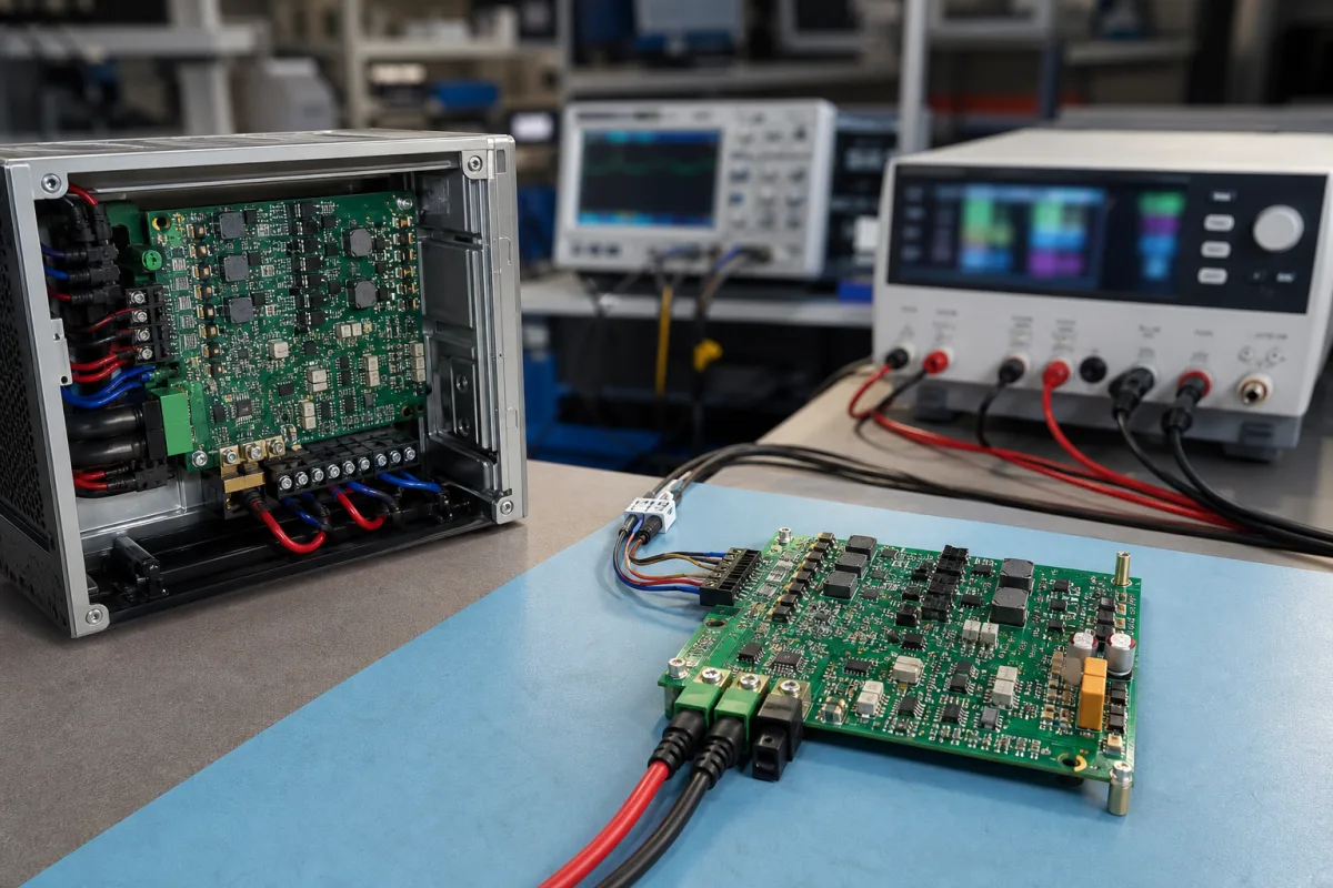
Power management ICs (PMICs) · Input sources and power path, number of rails and their type (buck, LDO, load switch), output current and accuracy, sequencing and control interface, protection, quiescent current, temperature and package
A power management IC (PMIC) combines multiple regulators — buck converters, LDOs and load switches — with sequencing, control and protection, and in some parts a battery charger, on one chip to power a processor and its memory, I/O and peripherals. Settle three things before choosing one: the rails, voltages and currents the processor and board need, the input sources, charger and power path, and the sequencing, interface, protection, quiescent current, temperature range and package.
Multi-rail power management ICs for processors, SoCs and portable or embedded systems, with integrated converters, LDOs, load switches and optional chargers. Single buck converters, single LDOs, VRMs, battery management systems and power-quality equipment are outside this page; buck converters, LDOs, VRMs and battery management systems have their own pages.
CNFX editorial research · Sources checked October 12, 2026 · 4 sources
TI's TPS65217 datasheet describes a single-chip PMIC designed to power the AM335x Arm Cortex-A8 processor in portable and 5 V line-powered applications, with three step-down converters (DCDC1–3) with integrated switching FETs at a fixed 2.25 MHz, power-save mode at light load, ±2% output accuracy in PWM mode, 100% duty cycle for lowest dropout and about 15 µA quiescent current each, rated 0–1.2 A output with a 1.6 A current limit; two adjustable LDOs (one able to track DCDC3) at about 15 µA quiescent; two load switches that can be configured as LDOs; and a WLED boost driver for two strings of up to 10 LEDs at 25 mA with 38 V open-LED protection. [1]
Etek Microelectronics lists LDOs, PMICs, buck, boost and buck-boost DC/DC converters, Li-battery and energy-harvest chargers and USB PD controllers in its power management range, alongside power protection devices. [2]
Editorial calculation: three buck rails at their 1.2 A rating — for example 1.1 V core, 1.5 V memory and 3.3 V I/O — can deliver up to 1.32 + 1.8 + 3.96 ≈ 7.1 W; total the expected load on each rail with margin and compare it with the input source and thermal limits of the package. [1]
Give the supplier the processor or SoC and its rail voltages, currents and sequencing, number and type of rails, input sources (USB, adaptor, battery) and charger needs, standby and sleep currents, control interface and register protection, protection and reset functions, LED or other drivers, temperature range, package and quantity.
02
Check inputs, charger, control and protection
The TPS65217 accepts any combination of USB port, 5 V AC adaptor or Li-ion battery, with 20 V-tolerant USB and AC inputs, a 2 A power path and a linear charger up to 700 mA for single-cell Li-ion or Li-polymer with thermal regulation, safety timers and a temperature-sense input. Protection and control include undervoltage lockout, a battery-fault comparator, an always-on push-button monitor, a hardware reset pin and password-protected I²C registers (address 0x24); the device is characterised from −40 to 105 °C and comes in a 48-pin 6 × 6 mm VQFN with 0.4 mm pitch. [1]
Editorial note: sequencing and reset behaviour must match the processor's power-up requirements, so check the PMIC's default sequence (or factory variant) against the processor datasheet. [1]
03
Check the design-in details the PMIC maker publishes
ROHM's application note BD71837AMWV Frequently asked questions (No. 62AN067E, Rev.004, 2020) covers a PMIC for NXP i.MX 8M SoCs and answers board-level questions that a buyer should settle before layout. [3]
The note also states that BD71837MWV is no longer in mass production and points to the AMWV version, and that start-up behaviour is changed through the TRANS_COND0/1 registers. Use such notes alongside the processor maker's reference design and the PMIC datasheet. [3][1]
Editorial calculation: 3.3 V across about 33 mA implies about 100 Ω of discharge path; adding 60 kΩ in series limits the current to about 0.055 mA.
Design point (ROHM FAQ)
Answer given
BUCK6 inductor
Designed for 1 µH for best ripple and transient response; 0.47 µH possible if the degradation is acceptable
Output capacitors
BUCK7 (1.5 A) needs 22 µF; the other bucks (3 A) need 2 × 22 µF
I²C address
0x4B; REGLOCK register locks I²C access by default
Logic levels
DVDD must be 1.8 V; 3.3 V pull-ups and 3.3 V control signals are acceptable
Rail sequencing
BUCK8 (memory) de-asserted before BUCK7; BUCK8 voltage set by U-Boot for the DDR type
Unused BUCK6
Not recommended to disable: its output is a trigger for POR_B; if omitted, feed 3.3 V to BUCK6_FB via up to 60 kΩ to limit about 33 mA leakage
UVLO threshold
Fixed, not adjustable
Software power-down
De-assert PMIC_ON_REQ (via the SoC's SNVS_LPCR register)
Ask the PMIC supplier for the processor reference schematic, inductor and capacitor values per rail, the I²C address and lock behaviour, the default power-up sequence and how it is changed, and the part's production status.
04
Compare a higher-current PMIC: rail currents, voltage steps, factory configurations and package
SG Micro's SGM260320 product page describes a PMIC for solid-state drives, FPGAs, microcontroller applications and personal navigation devices, with three buck converters and two LDOs from a 2.7 V to 5.5 V input. Buck1 is rated 4 A and can be set as a load switch or bypass; Buck2 and Buck3 are rated 3 A; LDO1 and LDO2 are rated 300 mA. Outputs are programmable from 0.6 V to 2.991 V in 9.375 mV steps or from 0.8 V to 3.9875 V in 12.5 mV steps (Buck3 in the 0.8–3.9875 V range only). Sequencing, output voltage, switching frequency, start-up and soft-start time, sleep modes and current limit are configurable over I²C at up to 1 MHz, and the part ships with factory-programmed default configurations. [4]
The page lists four programmable GPIOs, with inputs for EXT_PG, DVS control, SYS_EN and load-switch-mode LDO control, and outputs for EXT_EN, nRESET, nIRQ and SYSMON; protection covers input and output over- and under-voltage, short-circuit, over-current and thermal shutdown. The package is a WLCSP measuring 2.42 × 2.82 mm with 36 bumps. [4]
Editorial calculation: (2.991 − 0.6) ÷ 0.009375 ≈ 255 steps and (3.9875 − 0.8) ÷ 0.0125 = 255 steps, so each range is set by an 8-bit code. The rails add up to 4 + 3 + 3 + 0.3 + 0.3 = 10.6 A, against 3 × 1.2 A of buck current on the TPS65217. At assumed rail voltages of 1.0 V, 1.8 V and 3.3 V on the three bucks at full current, output power is about 19.3 W; at an assumed 90% efficiency from a 5 V input that is about 4.3 A of input current through a 6.8 mm² package. Ask the supplier which factory configuration matches your sequence, for the thermal derating of the WLCSP on your board, and for the input-current limit of your 5 V source. [4][1]
0.6–2.991 V, 9.375 mV; or 0.8–3.9875 V, 12.5 mV. [4]
05
PMICs listed beside LDOs, DC/DC converters, chargers and PD controllers
The listings reviewed cover LDOs, PMICs, DC/DC converters, chargers and PD controllers. Ask each for the datasheet, the processor reference design it supports and the default sequencing options. [2]
06
Buck, LDO, charger, sequencer, I²C and UVLO blocks of the TPS65217
Input range, rail voltage and current, switching frequency and external parts for a PMIC order
Published values here come from the TPS65217 datasheet and, for inductors and capacitors, ROHM's i.MX 8M FAQ; humidity, IP rating and isolation do not apply to a board-level IC.
Field
What it means and published values
Ask the supplier for
Input Voltage Range
USB, 5 V adaptor or Li-ion; 20 V tolerant inputs. [1]
10 companies list this product among what they make. Company figures are quoted from each
company's own website; every card states where the relationship came from.
ETEK Microelectronics
Manufacturing site to be confirmed for the order
Lists LDOs, PMICs, DC/DC converters, chargers and PD controllers.
Explore company information and manufacturing capabilities, then discuss the scope of your project with a relevant supplier.
Share this page
Compiled and source-reviewed by the CNFX editorial team.
Each manufacturer above links to the page on that company's own website where the product is listed, with the date we checked it. How we source and review
· Page last updated 13 October 2026
Buyer questions
What does a PMIC integrate?
TI's TPS65217 integrates three buck converters, two LDOs, two load switches, a Li-ion charger with power path and a WLED driver. [1]
How much current can each PMIC rail deliver?
The TPS65217's buck converters are rated up to 1.2 A each, with ±2% accuracy in PWM mode. [1]
Can a PMIC charge a battery?
Yes; the TPS65217 includes a linear charger up to 700 mA for single-cell Li-ion or Li-polymer. [1]
How is a PMIC configured?
The TPS65217 uses I²C with password-protected registers. [1]
Can an unused PMIC buck rail simply be left off the board?
Not always: ROHM's FAQ for the BD71837AMWV says BUCK6 is monitored for the power-good signal and, if omitted, its feedback pin must be held at 3.3 V through up to 60 kΩ. [3]
How much current can a multi-rail PMIC supply?
SG Micro's SGM260320 lists 4 A, 3 A and 3 A bucks and two 300 mA LDOs (10.6 A in total), while TI's TPS65217 bucks are rated 1.2 A each. [4][1]
Sources and what still needs a direct check
Sources checked 2026-10-12. Texas Instruments' TPS65217 datasheet and SG Micro's SGM260320 product page are used for PMIC specifications, and ROHM's application note for design-in details; Etek is a linked supplier whose product range is cited.