Fibre optic connector polishing machines · Connector and ferrule types per fixture, PC, UPC and APC end-face geometry (radius of curvature, apex offset, fibre undercut or protrusion), back reflection and insertion loss, polishing motion, films, pressure control and inspection
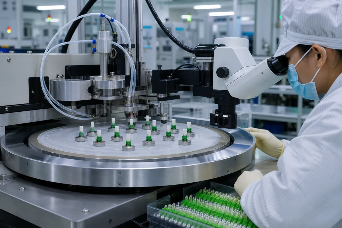
A precision fibre optic polishing machine grinds and polishes the end faces of terminated connector ferrules (or bare fibres) on a sequence of lapping films, holding the ferrules in a fixture at a set pressure and moving them in a controlled pattern so the end face reaches the dome radius, apex position and fibre height that low loss and low back reflection need. Ask three things first: which connectors, ferrule sizes and polish types (PC, UPC, APC) the machine must handle, what end-face geometry and optical performance the assemblies must meet and how they are inspected, and how many connectors per cycle and how much process control (pressure, speed, time) production needs.
Polishing machines for fibre optic connectors, ferrules, military termini and bare fibres, from portable units to mass-production polishers, with their fixtures. Ferrules themselves (see precision fibre optic ferrule), fusion splicers, end-face interferometers and inspection microscopes sold separately, and polishing films and slurries are outside this page except where compared.
CNFX editorial research · Sources checked October 12, 2026 · 4 sources
Krell Technologies' SpecPro data sheet states that it polishes connectors and military termini to Telcordia compliance and lists, for connectors, apex offset below 50 µm; radius of curvature of 10–25 mm for 2.5 mm ferrules, 7–20 mm for 1.25 mm ferrules and 5–12 mm for APC ferrules; and undercut/protrusion of 0 to −50 nm. It quotes back reflection below −55 dB for UPC and below −65 dB for APC and insertion loss below 0.25 dB, noting that optical performance may vary between connector manufacturers. It also polishes bare fibres of 80 µm to over 1.5 mm with adapters. [1]
Nanometer Technologies' MCP-24 listing gives radius of curvature 7–30 mm, apex offset below 50 µm, undercut/protrusion below 50 nm and back reflection of −35 to −65 dB, and lists polish styles including PC, UPC, 8° and 10° APC, flat, spherical, radius and domed, on ceramic, glass, stainless steel and plastic ferrules, with a universal fixture for FC, SC, ST, FDDI, E2000 PC and other 2.5 mm ferrules and over 40 fixture-plate styles. [2]
Editorial calculation: back reflection (return loss) in dB converts to a power ratio of 10^(dB/10); −55 dB is about 3.2 × 10⁻⁶ of the incident power and −65 dB about 3.2 × 10⁻⁷, so an APC end face at −65 dB reflects about one-tenth of what a UPC end face at −55 dB reflects. [1]
Senko's application note Polishing Best Practices (Rev. 01, November 2023) tabulates the limits the machines must hit. For PC ferrules, GR-326-CORE Issue 4 gives radius of curvature 7–25 mm, apex offset below 50 µm and protrusion up to 50 nm; IEC 61755-3-1 gives 10–25 mm, below 70 µm and 100 nm; for APC both give 5–12 mm, below 70 µm and 100 nm protrusion, with a −100 nm undercut limit. For PC undercut both use U = −0.02R³ + 1.3R² − 31R + 325 (nm, R in mm). [3]
Editorial calculation: with that formula, a 15 mm radius allows about 85 nm of undercut (−67.5 + 292.5 − 465 + 325), and a 20 mm radius about 65 nm (−160 + 520 − 620 + 325); a tighter radius tolerates a deeper recess. [3]
Editorial note: the geometry limits quoted by these makers are their claimed capability; ask for the acceptance criteria your customers specify and for interferometer reports on sample connectors polished on the offered machine.
Give the supplier the connector types and ferrule diameters, polish types (PC, UPC, APC 8°), single-mode or multimode, end-face geometry limits (radius, apex offset, fibre height), optical limits (insertion loss, back reflection), connectors per cycle and daily volume, fixtures needed, film sequence, pressure and timing control, inspection integration, power supply and portability.
02
Set capacity, motion and process control
The SpecPro is a portable machine for low-volume manufacturing and field use: up to 4 connectors, independently suspended and optically aligned workholders (universal UPC workholders for ferrules of 1.25–3.2 mm), 4 in polishing films, random orbital motion, a user-adjustable digital cycle timer, in-line video inspection with a separate videoscope, 100–240 V AC or 9 V battery supply, a 7 × 4.5 in footprint and about 4.5 lb. [1]
The MCP-24 listing describes polishing up to 48 connectors at a time with a patented figure-8 pattern that controls radius, apex offset and fibre undercut, a pneumatic pressure system, and suitability for high-volume single-mode and multimode polishing. [2]
Editorial note: for production, ask how polishing pressure, speed and time are set and stored for each film step, how fixture wear is checked, and what yield the supplier achieves on your connector type.
Domaille Engineering's APM-HDC-5400 shows the controls a production polisher adds. Its product page lists pneumatically controlled polishing pressure of up to 24 lb, with automatic adjustment for the number of connectors loaded in the fixture; a standard 5 in platen with an 8 in option; a bi-directional platen; programmable pressure and speed ramps, auto-start of successive pressure and speed steps on one film, a film change counter and a maintenance section; a touch-screen interface storing unlimited processes, with USB transfer between machines and password-protected configuration; operator prompts for film, pad and lubricant; and a 100–240 V AC, 50/60 Hz supply with CE marking. Fixtures for single- and multi-fibre connectors are sold separately. [4]
Editorial calculation: 24 lb is about 24 × 4.448 ≈ 107 N of total force; shared across an assumed 12-connector fixture, that is about 8.9 N per connector, which is why the machine scales pressure to the number loaded. Moving from the 5 in to the 8 in platen gives (8 ÷ 5)² ≈ 2.6 times the film area. The connector count is an example; ask the supplier for the per-connector force each process step uses. [4]
Senko adds that polishing films sit on rubber pads graded from 50 to 95 Shore in steps of 5, that pads harden as they dry out, and that a softer pad lowers the radius of curvature. From its production data, one full polishing cycle removes about 0.05 mm of ferrule length on a 1.25 mm ferrule, so connectors can be re-polished about two to three times; 2.5 mm ferrules have twice the material, allowing four to five. Diamond films remove about 80% of the material in a UPC polish, and the pedestal diameter must not grow more than 0.1 mm. [3]
03
Find fibre optic polishing machine manufacturers
Krell, Nanometer Technologies and Domaille appear on this page as sources for their published machine data, not as reviewed supplier cards. Whichever polisher maker you approach, ask for interferometer results on your own connectors from every fixture position.
04
Which machine parts control radius, apex and fibre height
Explore company information and manufacturing capabilities, then discuss the scope of your project with a relevant supplier.
Share this page
Compiled and source-reviewed by the CNFX editorial team.
Each manufacturer above links to the page on that company's own website where the product is listed, with the date we checked it. How we source and review
· Page last updated 13 October 2026
Buyer questions
What end-face geometry should a polished connector meet?
Machine makers quote apex offset below 50 µm, radius of curvature in ranges such as 7–25 mm depending on ferrule, and fibre height within about 50 nm; confirm limits with your customer's specification. [1][2]
How many connectors can a polishing machine handle at once?
From 4 on one portable unit to 48 on one mass-production polisher. [1][2]
What back reflection can APC polishing reach?
One maker quotes below −65 dB for APC and below −55 dB for UPC. [1]
How many times can a connector be re-polished?
Senko's 2023 application note says about two to three times for 1.25 mm ferrules, since each cycle removes about 0.05 mm, and four to five times for 2.5 mm ferrules. [3]
How much polishing pressure does a production fibre polisher apply?
Domaille lists up to 24 lb of pneumatically controlled pressure for its APM-HDC-5400, adjusted automatically for the number of connectors in the fixture. [4]
Sources and what still needs a direct check
Sources checked 2026-10-12. The Krell, Nanometer and Domaille sources are maker or distributor descriptions of their own machines and quote claimed capability, and SENKO's application note tabulates the industry geometry limits. Acceptance limits for your assemblies come from your customer's standard, and results must be shown on your connectors.