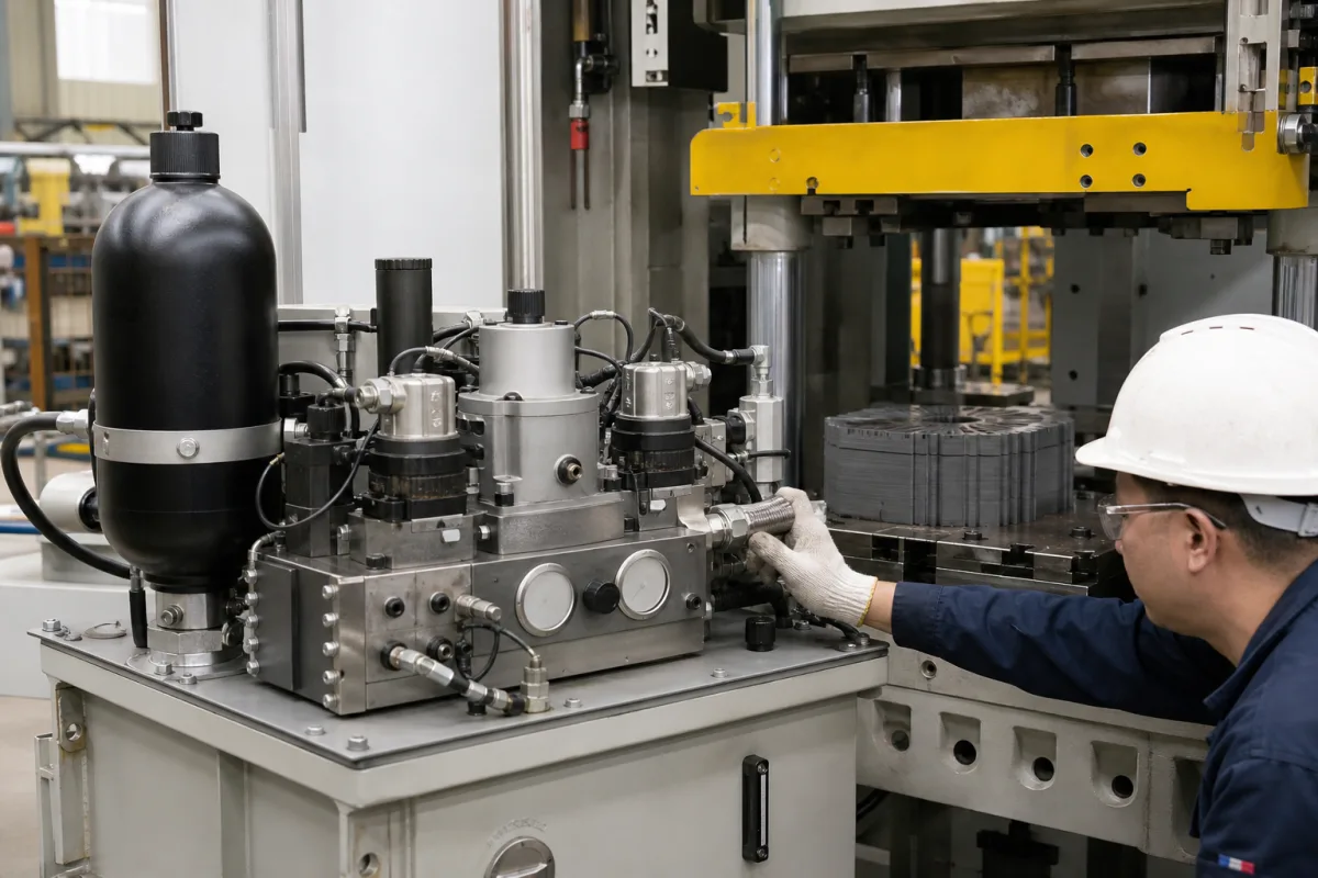
A hydraulic pressure control system is the valve manifold, proportional pressure valve, pressure transmitter, accumulator and controller on a press power unit that turn a pressure setpoint into a held clamping or pressing force, for example when stacking and pressing transformer or motor core laminations. Ask three things first: what accuracy the proportional valve gives on its own, whether a transmitter closes the loop and how fast, and how the accumulator is pre-charged to hold pressure during dwell.
Electro-hydraulic pressure control assemblies for presses and clamping fixtures: proportional pressure relief and reducing valves with their electronics, pressure transmitters, bladder accumulators, manifolds and controllers. The vacuum and pressure systems of resin impregnation vessels for windings are covered on the Vacuum pressure impregnation (VPI) chamber page. Pneumatic regulators, refinery process control valves and complete presses are outside this page.
CNFX editorial research · Sources checked October 12, 2026 · 3 sources
Bosch Rexroth's data sheet RE 29162 (2025-04) for its direct-operated DBET/DBETE proportional pressure relief valve lists maximum set pressures of 50, 100, 200, 315, 350 and 420 bar at a maximum flow of 2 l/min. As percentages of maximum set pressure it gives hysteresis below 4%, range of inversion below 0.5%, linearity of ±3%, and a manufacturing tolerance at 100% command of below ±1.5% for the DBETE with integrated electronics against below ±5% for the DBET. Step response from 0 to 100% and back is 80 ms, system dependent, measured with under 20 cm³ of line volume. [1]
The same sheet requires hydraulic fluid cleanliness of ISO 4406 class 20/18/15, recommends 30–46 mm²/s viscosity, rates the valve IP65, and takes a 24 V DC supply with a 0–10 V or 4–20 mA command signal. [1]
Editorial calculation: on a 315 bar valve, hysteresis under 4% allows up to about 12.6 bar between rising and falling commands, and linearity of ±3% about ±9.5 bar; where a press needs its setpoint held tighter than that, the valve has to be trimmed by a pressure transmitter in a closed loop. [1]
Give the supplier the press force and cylinder area (so pressure can be converted to force), the pressure range and required accuracy at the setpoint, ramp and dwell times, flow to be relieved, oil type and cleanliness target, supply voltage and the controller or PLC signals.
02
Close the loop with a pressure transmitter
SensorsONE's data sheet for the 17.620G OEM pressure transmitter, listed for mobile hydraulics and presses, covers ranges from 0–16 to 0–600 bar with accuracy of ≤ ±0.5% FSO under IEC 60770 (limit point, including non-linearity, hysteresis and repeatability), a typical response time of 2 ms and thermal error of ≤ ±0.2% FSO per 10 K between −20 and 80 °C. [2]
For the 0–400 bar range it gives 800 bar static overpressure and at least 2,000 bar burst pressure, a 316L pressure port, 4–20 mA two-wire output on 10–30 V DC, and an operational life of more than 100 million pressure cycles. [2]
Editorial calculation: a 0–400 bar transmitter at ±0.5% FSO reads to ±2 bar; its typical 2 ms response is a small fraction of the valve's 80 ms step response, so the loop speed is set by the valve and hydraulics rather than the sensor. [2][1]
03
Pre-charge the accumulator for the pressure band
HYDAC's bladder accumulator brochure limits gas pre-charge to p0 ≤ 0.9 × p1 with a permitted pressure ratio p2 : p0 ≤ 4 : 1, where p2 is the maximum operating pressure, and treats these as maximum values, not a permanent load. It requires charging with nitrogen only, at least class 4.0 (filtration < 3 µm), gives a standard operating temperature of −10 to +80 °C, and lists high-flow SB330 units at up to 30 l/s and SB600 units to 345 bar. [3]
Editorial calculation: with a minimum working pressure p1 of 200 bar, pre-charge may be at most 180 bar. For a 10 L accumulator at p0 = 180 bar cycling between 200 and 300 bar, Boyle's law (isothermal, gauge values used in place of absolute) gives about 10 × 180 × (1/200 − 1/300) = 3.0 L of usable oil; ask the supplier to repeat the sizing with absolute pressures and the adiabatic case for fast discharge. [3]
Pressure range, valve and transmitter accuracy, step response and command signal for press pressure control
The accuracy figures here belong to single components (valve linearity ±3%, transmitter ±0.5% FSO); ask for the closed-loop result on your own circuit. [1][2]
Explore company information and manufacturing capabilities, then discuss the scope of your project with a relevant supplier.
Share this page
Compiled and source-reviewed by the CNFX editorial team.
Each manufacturer above links to the page on that company's own website where the product is listed, with the date we checked it. How we source and review
· Page last updated 13 October 2026
Buyer questions
How accurate is a proportional pressure valve on its own?
Bosch Rexroth's DBETE data sheet gives hysteresis below 4% and linearity of ±3% of maximum set pressure. [1]
How fast must the pressure transmitter be?
The 17.620G transmitter data sheet gives a typical 2 ms response, against the valve's 80 ms step response. [2][1]
What pre-charge does a bladder accumulator need?
HYDAC limits pre-charge to 0.9 × the minimum operating pressure and the maximum-to-pre-charge ratio to 4:1, using nitrogen only. [3]
Sources and what still needs a direct check
Sources checked 2026-10-12. Bosch Rexroth and HYDAC data sheets describe their own valves and accumulators. SensorsONE publishes the transmitter data sheet.