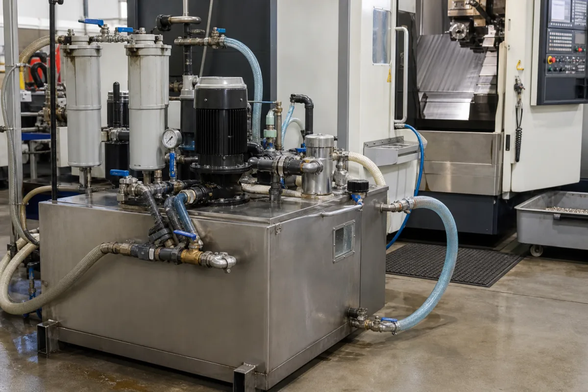
Coolant system for CNC machine tools: machine-side tank, filtration and flood-coolant supply unit
Machine-side coolant units · Return pump, fleece or cartridge filter, clean tank and flood supply pump beside a CNC machine; sump level, tramp oil and mist
A coolant system, in the sense used on this page, is the unit standing beside a CNC lathe, machining centre or drilling machine that receives the dirty cutting fluid running off the machine, separates chips and fines in a filter, holds the cleaned fluid in a tank and pumps it back to the flood nozzles. What decides whether it works is how fine the filter is against the material being cut, how much clean fluid the tank holds against the return flow, and how the sump is kept topped up, skimmed and covered.
Machine-side coolant tanks and supply units for CNC lathes, machining centres and drilling machines that return, filter, store and deliver cutting fluid at flood pressure: return or transfer pumps, fleece, cartridge and other filters, clean and dirty tanks, skimmers, level and concentration care, and the flood supply pump. Through-spindle and through-tool coolant units with high-pressure pumps, their filtration for those pumps and their chillers are covered on the High-pressure coolant systems page; where one unit carries both, this page deals with the tank and filtration side. Aluminium profile drilling machines are covered on the Aluminium profile drilling machine page. Spindle cooling circuits, mist collectors and central coolant plants serving whole halls are outside this page.
CNFX editorial research · Sources checked October 12, 2026 · 3 sources
Match filter fineness and flood-pump flow to the material being cut
Brinkmann's data sheet for its TFS3 screw spindle pumps recommends filtration below 50 µm for turning, milling and drilling and below 20 µm for grinding and for machining aluminium. The pumps take filtered, lubricating fluids such as coolant oils and water-soluble coolants of 1 to 45 mm²/s with at most 3 to 5% air by volume, and are not designed for dry running, so the tank has to keep the suction covered. [2]
At the low end of its pressure range, the TFS348 at 2,900 min⁻¹ delivers 60 l/min at 10 bar with a 1 mm²/s fluid and 62.3 l/min with a 20 mm²/s fluid, drawing 1.5 to 1.6 kW from a 2.2 kW motor; the pump with its motor weighs 47 kg. At 20 bar it gives 58.5 to 61.5 l/min and needs a 4.0 kW motor. [2]
Editorial calculation: 60 l/min is 0.001 m³/s, so at 10 bar (1,000,000 Pa) the fluid receives 1.0 kW, about two-thirds of the 1.5 kW power consumption listed at 1 mm²/s. [2]
Give the supplier the machine type and its coolant return and supply connections, the fluid (emulsion, synthetic or neat oil, with viscosity), the material and finest chips cut, the target filter fineness, the flood flow the nozzles need, available floor space and power supply, and whether a cooler is wanted. If the machine also needs through-spindle coolant, say so and ask whether the high-pressure stage is quoted separately.
02
Keep the sump topped up, skimmed and covered
OSHA's metalworking fluids manual says a sump level 30% below the full mark points to fluid loss or water evaporation, and that the concentration should then be checked and corrected. If tramp oil covers a water-diluted sump again within 5 to 8 seconds of being swished aside, there is too much and it should be skimmed or pumped off. [3]
The manual lists OSHA's permissible exposure limits of 5 mg/m³ (8-hour TWA) for mineral oil mist and 15 mg/m³ for particulates not otherwise classified, and cites NIOSH's 1998 recommended limit of 0.4 mg/m³ thoracic particulate (about 0.5 mg/m³ total particulate) for metalworking fluid aerosols. It names low-pressure delivery, minimising flow and covering reservoirs and return systems among ways to reduce mist, gives an example of intermittent flow of 30 seconds on and 2 minutes off for moving chips, and advises against fluid standing still for more than 8 to 10 hours. [3]
Editorial calculation, assuming a 150 l clean tank like Knoll's fed to a flood pump delivering 60 l/min like the TFS348 at 10 bar: the clean fluid is turned over every 150 ÷ 60 = 2.5 minutes, so ask how the filter and return pump are sized to keep up with that flow. [1][2]
03
Fleece belt filter, clean tank and flood delivery in one unit
Element
What the source describes
Ask about
Fleece compact filter with sludge container
Transfer pump lifts dirty fluid from the machine to the filter; spent fleece drops into a sludge container; filter fineness up to 20 µm. [1]
Fleece use per shift; fineness.
Clean tank
Filtered fluid collects in the clean media tank, 150 l in one unit. [1]
Volume; level sensing.
Flood supply pump
Screw spindle pump at 10 bar, 60 l/min; not for dry running. [2]
Flow at your viscosity.
Covered reservoir and return
Covering reservoirs and return systems listed among mist controls. [3]
Covers; return routing.
04
From return pump and filter through the clean tank to the flood nozzles
Explore company information and manufacturing capabilities, then discuss the scope of your project with a relevant supplier.
Share this page
Compiled and source-reviewed by the CNFX editorial team.
Each manufacturer above links to the page on that company's own website where the product is listed, with the date we checked it. How we source and review
· Page last updated 13 October 2026
Buyer questions
How fine should coolant filtration be for aluminium?
Brinkmann recommends below 20 µm for grinding and machining aluminium and below 50 µm for general turning, milling and drilling. [2]
What does a flood supply pump draw at 10 bar?
Brinkmann lists 60 l/min at 10 bar for its TFS348, absorbing 1.5–1.6 kW on a 2.2 kW motor. [2]
What mist limits apply?
OSHA's manual gives a 5 mg/m³ PEL for mineral oil mist and cites NIOSH's 0.4 mg/m³ recommended limit for metalworking fluid aerosols. [3]
Sources and what still needs a direct check
Sources checked 2026-10-12. Knoll and Brinkmann are makers publishing data for their own units and pumps; OSHA's manual is US government guidance on metalworking fluids.