Editorial Technical Reference

Precision Positioning Stage

This page explains how Precision Positioning Stage is classified within Computer, Electronic and Optical Product Manufacturing. Technical values and manufacturer relationships are research references; confirm the current specification and supplier evidence for each order.

Technical Definition & Core Assembly

A high-precision mechanical platform that provides controlled, nanometer-scale movement for positioning optical components or samples within an Optical Surface Analyzer.
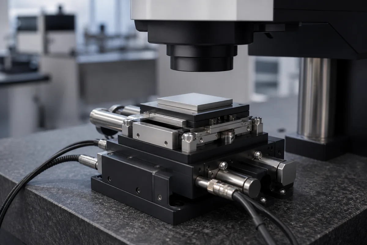
Precision Positioning Stage in a manufacturing environment
Representative product image. Confirm appearance and specifications with the manufacturer.

Product Specifications

Technical details and manufacturing context for Precision Positioning Stage

Definition
The Precision Positioning Stage is a critical component of an Optical Surface Analyzer, responsible for accurately positioning optical elements (such as lenses, mirrors, or the sample under test) with sub-micron or nanometer precision. It enables the analyzer to perform precise scans, measurements, and alignments required for surface topography analysis, ensuring repeatability and accuracy in data acquisition. The stage is typically constructed with an aluminum alloy body, stainless steel guide rails and screws, and ceramic bearing elements. It offers a standard XY travel range of 100–200 mm, with custom ranges available. Positioning accuracy is ±0.1 µm unidirectional, and bidirectional repeatability is ±0.05 µm. Closed-loop control with a linear encoder provides a resolution of 0.01 µm. The stage supports a maximum load of 10–20 kg in horizontal orientation, with a maximum speed of 50–100 mm/s at full load. Over full travel, straightness and flatness are each ±0.5 µm, and pitch, roll, and yaw are each ±2 arcsec. Operating temperature ranges from 10–40 °C (non-condensing), and relative humidity from 20–80% RH (non-condensing). The stage has an ingress protection rating of IP54 per IEC 60529, indicating dust and splash resistance. Depending on configuration, the weight is 15–25 kg. This component is essential for applications requiring high precision and stability, such as semiconductor inspection, metrology, and research. When selecting a stage, verify model-specific values and standards with the legal manufacturer or supplier, as the listed parameters are reference ranges for typical configurations.
Working Principle
The stage uses piezoelectric actuators, linear motors, or precision lead screws driven by servo or stepper motors. A closed-loop control system, often incorporating optical encoders or laser interferometers for position feedback, compares the actual position with the commanded position and adjusts the drive signals to minimize error, achieving precise linear or rotational motion. The control system continuously monitors position and corrects for deviations, ensuring high accuracy and repeatability. The choice of actuator and feedback mechanism depends on the required speed, load, and precision. The stage operates within specified environmental conditions to maintain performance.
Common Materials
Aluminum alloy (for the stage body), Stainless steel (for guide rails and screws), Ceramic (for bearing elements)
Technical Parameters
ParameterTypical rangeNotes & selection driver
Travel Range100–200 mmStandard XY travel; custom ranges available
Positioning Accuracy±0.1 µmUnidirectional repeatability
Repeatability±0.05 µmBidirectional
Resolution0.01 µmClosed-loop with linear encoder
Maximum Load10–20 kgHorizontal orientation
Maximum Speed50–100 mm/sAt full load
Straightness±0.5 µmOver full travel
Flatness±0.5 µmOver full travel
Pitch and Roll±2 arcsecOver full travel
Yaw±2 arcsecOver full travel
Operating Temperature10–40 °CNon-condensing
Relative Humidity20–80 % RHNon-condensing
Ingress ProtectionIP54Dust and splash resistantIEC 60529
Weight15–25 kgDepending on configuration

Ranges are indicative industry figures for RFQ preparation, not a supplier commitment. Confirm every value and standard with the legal manufacturer before ordering.

Components / BOM
  • Stage Platform (Top Plate) Part
    The mounting surface for optical components or the sample. Provides a flat, rigid reference plane.
    Material: Aluminum alloy or granite
  • Linear Guide / Bearing System
    Provides smooth, low-friction linear motion along one or more axes. Constrains movement to the desired degrees of freedom.
    Material: Stainless steel (rails) with ceramic or steel balls/rollers
  • Drive Mechanism (Actuator)
    Generates the force to move the stage. Common types include piezoelectric actuators, linear motors, or precision ball screws driven by rotary motors.
    Material: Varies (e.g., piezoelectric ceramic, copper windings, steel screw)
  • Position Sensor (Encoder/Interferometer)
    Measures the actual position of the stage with high resolution and provides feedback to the control system.
    Material: Glass scale (for optical encoder) or optical components (for interferometer)
  • Base / Frame Part
    Provides a rigid and stable foundation for the entire stage assembly, isolating it from external vibrations.
    Material: Granite, cast iron, or damped aluminum
  • Motion Controller
    Compares commanded position with the encoder reading and trims the drive — the loop behind nanometre accuracy.

Applied To / Applications

This component is essential for the following industrial systems and equipment:

Industrial Ecosystem & Supply Chain Structure

Complementary Systems
Downstream Applications
Specialized Tooling

Application Fit & Sizing Matrix

Operational Limits
pressure: Atmospheric pressure only (non-pressurized environment)
other spec: Vibration tolerance: <0.1g RMS, Humidity: 20-80% non-condensing, Cleanliness: Class 1000 or better recommended
temperature: 15°C to 30°C (operating), 0°C to 50°C (storage)
Media Compatibility
✓ Clean dry air environments ✓ Vacuum chambers (if vacuum-rated version) ✓ Inert gas atmospheres (N2, Ar)
Unsuitable: Wet or corrosive chemical environments (acids, bases, solvents)
Sizing Data Required
  • Travel range requirement (X, Y, Z axes in mm)
  • Load capacity (mass in kg)
  • Positioning accuracy/repeatability specification (in nm)

Reliability & Engineering Risk Analysis

Failure Mode & Root Cause
Positional drift
Cause: Encoder feedback degradation due to contamination, thermal expansion mismatches, or bearing wear affecting alignment
Stiction or erratic motion
Cause: Lubricant breakdown in linear guides/ball screws, particulate contamination in precision surfaces, or servo motor feedback loop instability
Maintenance Indicators
  • Audible grinding or clicking during motion, indicating mechanical wear or contamination
  • Visible position overshoot or hunting during settling, suggesting control loop or feedback issues
Engineering Tips
  • Implement regular precision alignment checks and thermal compensation calibration to maintain positioning accuracy
  • Maintain strict cleanliness protocols and use specified lubricants with scheduled reapplication to prevent contamination and stiction

Indicative industry ranges for design and RFQ preparation. Confirm the exact figures and applicable standard with the manufacturer before specifying.

Compliance & Manufacturing Standards

Applicable Standards
ISO 230-2:2014 (Test code for machine tools - Determination of accuracy and repeatability of positioning of numerically controlled axes) ANSI/ASME B5.54-2005 (Methods for Performance Evaluation of Computer Numerically Controlled Machining Centers) DIN 876-1:1986 (Straightedges and squares - Straightedges - Requirements, testing)

Quoted from the published standard.

Manufacturing Precision
  • Positioning accuracy: ±0.5 μm over full travel
  • Flatness of mounting surface: 2 μm per 100 mm
Quality Inspection
  • Laser interferometer positioning accuracy verification
  • Coordinate measuring machine (CMM) geometric error assessment

Manufacturers of Precision Positioning Stage

Manufacturer profiles associated with Precision Positioning Stage.

Sourcing Precision Positioning Stage from China?
Tell us your specification and target quantity — we will match it against manufacturer records and come back with the factories that fit.
Request manufacturers We manufacture this

Manufacturer listings support early research and capability understanding. They are not certification, ranking, or transaction guarantees.

Share this page
Technical documentation
Request current drawings, revision history, and a signed specification sheet.
Manufacturing capability
Verify equipment lists, process limits, capacity, and representative production evidence.
Inspection readiness
Confirm test methods, calibrated equipment, sampling plans, and traceable reports.
Supplier transparency
Check the legal entity, factory address, ownership, certifications, and direct contacts.

CNFX does not score or rank suppliers. Buyers must verify all claims and documents with the legal manufacturer before ordering.

Supply Chain Compatible Machinery & Devices

Industrial Smart Camera Module

The Industrial Smart Camera Module is a compact, self-contained vision processing unit designed for integration into industrial machinery and production lines.

Explore Specs →
Surface Mount Resistor

Passive electronic component for current limiting and voltage division in circuits

Explore Specs →
Surface Mount Capacitor

A surface mount capacitor is a fundamental electronic component used for energy storage, filtering, coupling, and decoupling in electronic circuits.

Explore Specs →
Surface Mount Technology (SMT) Pick-and-Place Machine

Automated machine that precisely places electronic components onto printed circuit boards.

Explore Specs →

Frequently Asked Questions

What is the travel range of the Precision Positioning Stage?

The standard XY travel range is 100–200 mm, with custom ranges available. Verify the exact range for your specific model with the manufacturer.

What is the positioning accuracy and repeatability?

Unidirectional positioning accuracy is ±0.1 µm, and bidirectional repeatability is ±0.05 µm. These values are reference ranges; confirm for your configuration.

What feedback system does the stage use?

The stage typically uses a closed-loop control system with optical encoders or laser interferometers for position feedback, achieving a resolution of 0.01 µm.

What is the maximum load capacity?

The maximum load is 10–20 kg in horizontal orientation. Ensure your application load is within this range and verify with the supplier.

Data Basis

Editorial classification, named public sources where available, and source-reviewed manufacturer records.

Preliminary Technical Classification
This page supports structured research, RFQ preparation, and supplier evaluation. It does not replace buyer-led supplier qualification, standards review, or technical approval.
Buyer enquiry

Request manufacturing insight for Precision Positioning Stage

Ask for use case, specification boundaries, supplier type, and RFQ preparation information for this product.

Where it goes
Straight to the CNFX editorial desk, and to the manufacturer if this product is linked to a claimed profile. Nothing is broadcast to a supplier list.
Your details stay here
We do not sell or rent enquiry data, and we do not add you to a mailing list. Used only to answer this request.
No commission, no middleman
CNFX is a directory. We take no cut of any order and never negotiate on a supplier's behalf.
What we don't claim
A listing is not an endorsement. Qualify every supplier and verify every figure yourself before ordering.

Your business information is used only to process this request.

Thank you! Your message has been sent. We'll respond within 1–3 business days.
Sorry, we couldn't send your message. Please try again, or email us at [email protected].

Need to Manufacture Precision Positioning Stage?

Compare manufacturer profiles with relevant product and process capability.

Previous Product
Precision Optical Lens Inspection and Measurement System
Next Product
Precision Pressure Transducer Sensing Element
Get QuotesChat