Editorial Technical Reference

Protocol PHY Chip

This page explains how Protocol PHY Chip is classified within Computer, Electronic and Optical Product Manufacturing. Technical values and manufacturer relationships are research references; confirm the current specification and supplier evidence for each order.

Technical Definition & Core Assembly

A semiconductor component that implements the physical layer (PHY) of a communication protocol within an interface module.
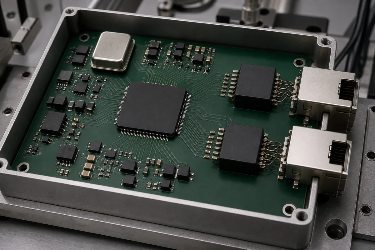
Representative product image. Confirm appearance and specifications with the manufacturer.

Product Specifications

Technical details and manufacturing context for Protocol PHY Chip

Definition
A Protocol PHY Chip is an integrated circuit that serves as the physical layer transceiver in an interface module, responsible for converting digital data into analog signals for transmission over physical media (such as copper cables or fiber optics) and vice versa for reception. It handles signal modulation, encoding, synchronization, and electrical/optical interfacing according to specific communication standards (e.g., Ethernet, USB, PCIe). This directory entry provides reference specifications for a typical industrial-grade PHY chip, including a supply voltage of 3.3 V ±10%, power consumption of 0.5–1.5 W at 100 Mbps, and support for data rates of 10/100/1000 Mbps per IEEE 802.3. The operating temperature range is -40 to 85 °C, storage temperature -55 to 125 °C, and junction temperature maximum rating -40 to 125 °C. The device is offered in a QFN-48 package with a 7x7 mm footprint (49 mm²), and has an ESD tolerance of ±8 kV (HBM) per IEC 61000-4-2. Humidity range is 5–95% RH non-condensing. The chip is fabricated on silicon. These values are typical reference ranges and must be verified against the specific model and application with the legal manufacturer or supplier. The chip operates by receiving digital data from the Media Access Control (MAC) layer, applying physical layer encoding (e.g., 8b/10b, 64b/66b), modulating it into electrical or optical signals suitable for the transmission medium, and driving these signals through the interface. On reception, it performs signal conditioning, clock recovery, demodulation, and decoding to reconstruct the digital data for the MAC layer. Selection inputs include required data rate, interface standard, power budget, and environmental conditions. Verification questions should address compliance with the relevant standard, actual power consumption, and thermal performance. Maintenance signals include monitoring for bit errors, link loss, and temperature excursions. Failure boundaries are defined by the absolute maximum ratings, such as junction temperature and ESD tolerance.
Working Principle
The chip operates by receiving digital data from the Media Access Control (MAC) layer, applying physical layer encoding (e.g., 8b/10b, 64b/66b), modulating it into electrical or optical signals suitable for the transmission medium, and driving these signals through the interface. On reception, it performs signal conditioning, clock recovery, demodulation, and decoding to reconstruct the digital data for the MAC layer. The physical medium may be copper or fiber, and the chip handles the necessary electrical or optical interfacing. The data rate is auto-negotiated according to IEEE 802.3, supporting 10/100/1000 Mbps. The chip's supply voltage is 3.3 V ±10%, and it operates within a temperature range of -40 to 85 °C. The device is designed for industrial environments, with an ESD tolerance of ±8 kV (HBM) and a humidity range of 5–95% RH non-condensing. The package is QFN-48 with a 7x7 mm footprint. These specifications are reference values and must be confirmed for the specific model.
Common Materials
Silicon
Technical Parameters
ParameterTypical rangeNotes & selection driver
Supply Voltage3.3 ±10% VOperating range for core and I/O
Power Consumption0.5–1.5 WTypical at 100 Mbps
Data Rate10/100/1000 MbpsAuto-negotiation supportedIEEE 802.3
Operating Temperature-40–85 °CIndustrial grade
Storage Temperature-55–125 °CNon-operating
ESD Tolerance±8 kVHBM modelIEC 61000-4-2
Package TypeQFN-487x7 mm
Footprint49 mm²QFN-48 package
Humidity Range5–95 % RHNon-condensing
Junction Temperature-40–125 °CMaximum rating

Ranges are indicative industry figures for RFQ preparation, not a supplier commitment. Confirm every value and standard with the legal manufacturer before ordering.

Components / BOM
  • Transmitter
    Converts digital data to analog signals and drives the transmission medium
    Material: Silicon
  • Receiver
    Amplifies, conditions, and converts incoming analog signals to digital data
    Material: Silicon
  • Clock Data Recovery (CDR) Circuit
    Extracts clock signal from the incoming data stream for synchronization
    Material: Silicon
  • Serializer/Deserializer (SerDes)
    Converts parallel data to serial for transmission and serial to parallel for reception
    Material: Silicon
  • Encoder/Decoder Block
    Applies the line coding (8b/10b, 64b/66b) on transmit and undoes it on receive.

Applied To / Applications

This component is essential for the following industrial systems and equipment:

Industrial Ecosystem & Supply Chain Structure

Complementary Systems
Downstream Applications
Specialized Tooling

Application Fit & Sizing Matrix

Operational Limits
voltage: 1.8V, 2.5V, 3.3V ±10% (core/supply)
data rate: Up to 10 Gbps (protocol-dependent)
temperature: -40°C to +125°C (operating), -55°C to +150°C (storage)
power consumption: Typically <500 mW active, <10 mW low-power modes
Media Compatibility
✓ Ethernet (copper/fiber) ✓ USB 3.0/3.1 ✓ PCI Express
Unsuitable: High-voltage industrial motor control environments (>50V transients)
Sizing Data Required
  • Protocol standard (e.g., 10GBASE-T, USB 3.2)
  • Interface type (copper, optical, backplane)
  • Power budget constraints

Reliability & Engineering Risk Analysis

Failure Mode & Root Cause
Electrostatic Discharge (ESD) Damage
Cause: Improper handling during installation or maintenance without proper grounding, leading to voltage spikes that degrade or destroy sensitive semiconductor components.
Thermal Overstress
Cause: Inadequate cooling or excessive ambient temperatures causing the chip to operate beyond its specified thermal limits, leading to accelerated aging, signal integrity loss, or permanent failure.
Maintenance Indicators
  • Intermittent or complete loss of network connectivity on the associated port, often accompanied by link status LED anomalies (e.g., flickering or off).
  • Abnormal heat emission from the chip or surrounding PCB area detected via thermal imaging or touch, indicating potential overheating.
Engineering Tips
  • Implement strict ESD protection protocols during all handling and maintenance, including use of grounded workstations, wrist straps, and anti-static packaging.
  • Ensure optimal thermal management by verifying heatsink attachment, maintaining clean airflow paths, and monitoring ambient temperature to stay within the chip's operating specifications.

Indicative industry ranges for design and RFQ preparation. Confirm the exact figures and applicable standard with the manufacturer before specifying.

Compliance & Manufacturing Standards

Applicable Standards
CE Marking - Electromagnetic Compatibility Directive 2014/30/EU

Quoted from the published standard.

Manufacturing Precision
  • Signal Integrity: +/- 5% jitter tolerance
  • Thermal Performance: +/- 2°C operating temperature range
Quality Inspection
  • Signal Integrity Testing (Eye Diagram Analysis)
  • Environmental Stress Screening (Temperature Cycling)

Manufacturers of Protocol PHY Chip

Manufacturer profiles associated with Protocol PHY Chip.

Sourcing Protocol PHY Chip from China?
Tell us your specification and target quantity — we will match it against manufacturer records and come back with the factories that fit.
Request manufacturers We manufacture this

Manufacturer listings support early research and capability understanding. They are not certification, ranking, or transaction guarantees.

Technical documentation
Request current drawings, revision history, and a signed specification sheet.
Manufacturing capability
Verify equipment lists, process limits, capacity, and representative production evidence.
Inspection readiness
Confirm test methods, calibrated equipment, sampling plans, and traceable reports.
Supplier transparency
Check the legal entity, factory address, ownership, certifications, and direct contacts.

CNFX does not score or rank suppliers. Buyers must verify all claims and documents with the legal manufacturer before ordering.

Supply Chain Compatible Machinery & Devices

Industrial Smart Camera Module

The Industrial Smart Camera Module is a compact, self-contained vision processing unit designed for integration into industrial machinery and production lines.

Explore Specs →
Surface Mount Resistor

Passive electronic component for current limiting and voltage division in circuits

Explore Specs →
Surface Mount Capacitor

A surface mount capacitor is a fundamental electronic component used for energy storage, filtering, coupling, and decoupling in electronic circuits.

Explore Specs →
Surface Mount Technology (SMT) Pick-and-Place Machine

Automated machine that precisely places electronic components onto printed circuit boards.

Explore Specs →

Frequently Asked Questions

What is a Protocol PHY Chip?

A Protocol PHY Chip is an integrated circuit that implements the physical layer of a communication protocol, converting digital data to analog signals for transmission and vice versa. It handles encoding, modulation, and interfacing with the physical medium.

What data rates does this PHY chip support?

According to the reference specifications, it supports 10/100/1000 Mbps with auto-negotiation, per IEEE 802.3. Actual support must be verified with the manufacturer for the specific model.

What is the operating temperature range?

The reference operating temperature range is -40 to 85 °C, suitable for industrial applications. Storage temperature is -55 to 125 °C, and junction temperature maximum is -40 to 125 °C.

What package is available?

The reference package is QFN-48 with a 7x7 mm footprint (49 mm²). Confirm the exact package and footprint with the supplier.

Data Basis

Editorial classification, named public sources where available, and source-reviewed manufacturer records.

Preliminary Technical Classification
This page supports structured research, RFQ preparation, and supplier evaluation. It does not replace buyer-led supplier qualification, standards review, or technical approval.
Buyer enquiry

Request manufacturing insight for Protocol PHY Chip

Ask for use case, specification boundaries, supplier type, and RFQ preparation information for this product.

Where it goes
Straight to the CNFX editorial desk, and to the manufacturer if this product is linked to a claimed profile. Nothing is broadcast to a supplier list.
Your details stay here
We do not sell or rent enquiry data, and we do not add you to a mailing list. Used only to answer this request.
No commission, no middleman
CNFX is a directory. We take no cut of any order and never negotiate on a supplier's behalf.
What we don't claim
A listing is not an endorsement. Qualify every supplier and verify every figure yourself before ordering.

Your business information is used only to process this request.

Thank you! Your message has been sent. We'll respond within 1–3 business days.
Sorry, we couldn't send your message. Please try again, or email us at contact@cnfx.com.

Need to Manufacture Protocol PHY Chip?

Compare manufacturer profiles with relevant product and process capability.

Previous Product
XY Positioning Stage
Last Product
Get QuotesChat