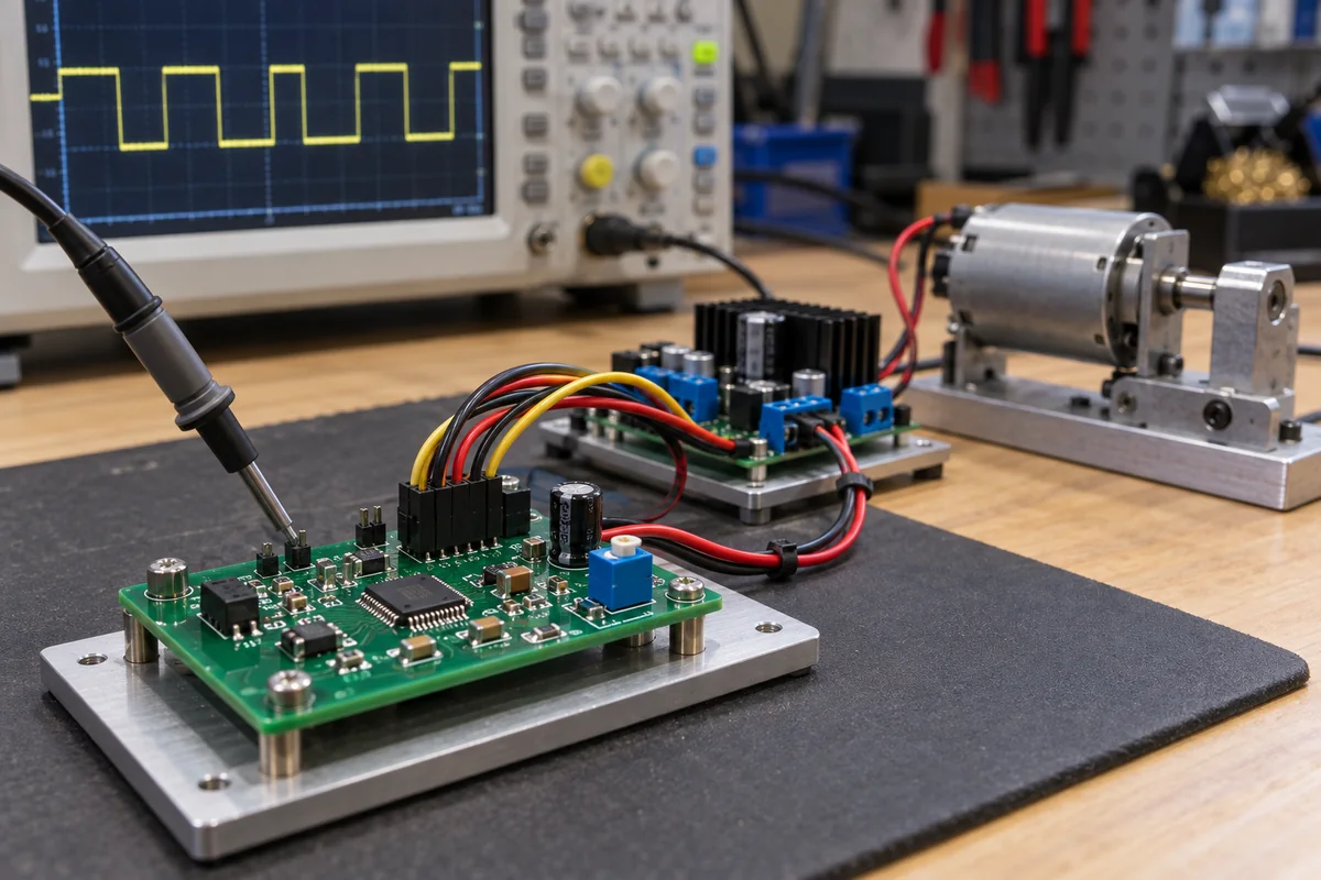
PWM generator board that feeds a motor driver: setting frequency and duty cycle the driver can accept
Logic-level PWM sources · 555 astable and pulse-width circuits, I²C 12-bit PWM controllers, matching frequency and pulse width to a motor driver input
The board in front of the motor driver does one job: produce a square wave whose frequency is fixed and whose high time can be set, from a potentiometer, a control voltage or a bus command. Whether that is a CMOS 555 timer or a dedicated PWM controller chip, the figure that decides success is at the other end of the cable — the driver's allowed input frequency and the shortest pulse it can detect.
Stand-alone PWM signal generator boards and modules that output logic-level pulse-width-modulated signals to motor drivers, LED drivers and servo inputs, built on timer ICs or dedicated PWM controller ICs. Microcontrollers that generate PWM in firmware are covered on the Microcontrollers (CPU / MCU) page; the power stage that switches the motor current belongs to the motor driver, and DMX512 LED decoders and BLDC motor drivers have their own pages.
CNFX editorial research · Sources checked October 17, 2026 · 3 sources
With a CMOS 555 in astable mode, the capacitor charges through RA and RB and discharges through RB, so two resistors and one capacitor set both frequency and duty cycle; TI notes that the charge and discharge times do not depend on the supply voltage. [1]
TI gives, for frequencies below 100 kHz, tH = 0.693 (RA + RB) C, tL = 0.693 RB C and a frequency of about 1.44 / ((RA + 2RB) C). Editorial calculation with the datasheet's own waveform example (RA = 5 kΩ, RB = 3 kΩ, C = 0.15 µF): 1.44 / (11 kΩ × 0.15 µF) ≈ 873 Hz, with the output high for (5 + 3)/(5 + 6) ≈ 73% of each period. [1]
For a voltage-controlled duty cycle the TLC555 can instead run as a triggered monostable with a control signal on CONT. TI warns that below 10% duty cycle output pulses may be inconsistent, and that close to 100% the output divides the frequency by 2, then 3, then 4. [1]
A dedicated controller replaces the RC network with a counter. NXP's PCA9685, sold as an LED controller, gives each of 16 outputs its own 12-bit (4096-step) PWM, at one shared frequency programmable from 24 Hz to 1526 Hz (typ.) off a 25 MHz (typ.) internal oscillator, set over I²C with duty from 0% to 100%. [2]
Its prescale value is round(25 MHz / (4096 × update rate)) − 1; the data sheet's example for 200 Hz gives 30 (0x1E), and the register limits are 0x03 for 1526 Hz and 0xFF for 24 Hz. Outputs are open-drain or totem-pole with 25 mA sink and 10 mA source at 5 V. [2]
Decide how the duty cycle is set in service — trimmer, control voltage or bus command — before choosing between a timer circuit and a PWM controller IC.
02
Pulse width the driver can still detect
The DRV8871 brushed-DC driver used as the example here accepts logic PWM on IN1 and IN2 from 0 to 200 kHz, at 0 to 5.5 V input level. [3]
Editorial calculation: at 20 kHz the period is 50 µs, so an 800 ns minimum pulse limits duty to about 1.6%–98.4%; at 200 kHz (5 µs period) the same 800 ns gives the 16%–84% the data sheet states. [3]
Editorial calculation: at the PCA9685's 1526 Hz maximum, one of 4096 steps lasts 1 / (1526 × 4096) ≈ 160 ns, so a pulse of fewer than 5 steps (800 / 160 = 5) falls under the DRV8871's 800 ns detection figure. The pairing is an illustration; check the actual driver's limit. [2][3]
Driver input condition
DRV8871 data sheet figure
Minimum pulse width to ensure detection
800 ns; TI adds "Typical devices require at least 400 ns" [3]
Paste it into your enquiry below or into an email to a maker, then replace every bracket.
Frequency: [Hz or kHz; fixed or adjustable]
Duty range and resolution: [%; steps]
Control input: [potentiometer; 0–5 V; I²C; other]
Channels: [number]
Output: [logic level V; push-pull or open-drain; mA]
Driver it feeds: [part; input frequency limit; minimum pulse]
Explore company information and manufacturing capabilities, then discuss the scope of your project with a relevant supplier.
Share this page
Compiled and source-reviewed by the CNFX editorial team.
Each manufacturer above links to the page on that company's own website where the product is listed, with the date we checked it. How we source and review
· Page last updated 17 October 2026
Buyer questions
What PWM frequency can a motor driver input accept?
It depends on the driver; the DRV8871 lists 0 to 200 kHz, with an 800 ns minimum pulse that narrows the usable duty cycle to 16–84% at 200 kHz. [3]
Can a 555 timer generate PWM for a motor?
Yes, in astable mode RA, RB and C set frequency and duty; TI warns of inconsistent pulses below 10% duty in its pulse-width-modulation circuit. [1]
Sources and what still needs a direct check
Sources checked 2026-10-17. Pulse generation: TI's TLC555 timer data sheet and NXP's PCA9685 PWM controller data sheet. Driver-side limits: TI's DRV8871 motor driver data sheet.