Editorial Technical Reference

Output Driver

This page explains how Output Driver is classified within Computer, Electronic and Optical Product Manufacturing. Technical values and manufacturer relationships are research references; confirm the current specification and supplier evidence for each order.

Technical Definition & Core Assembly

Electronic component that amplifies and conditions control signals to drive output devices in signal conversion systems.
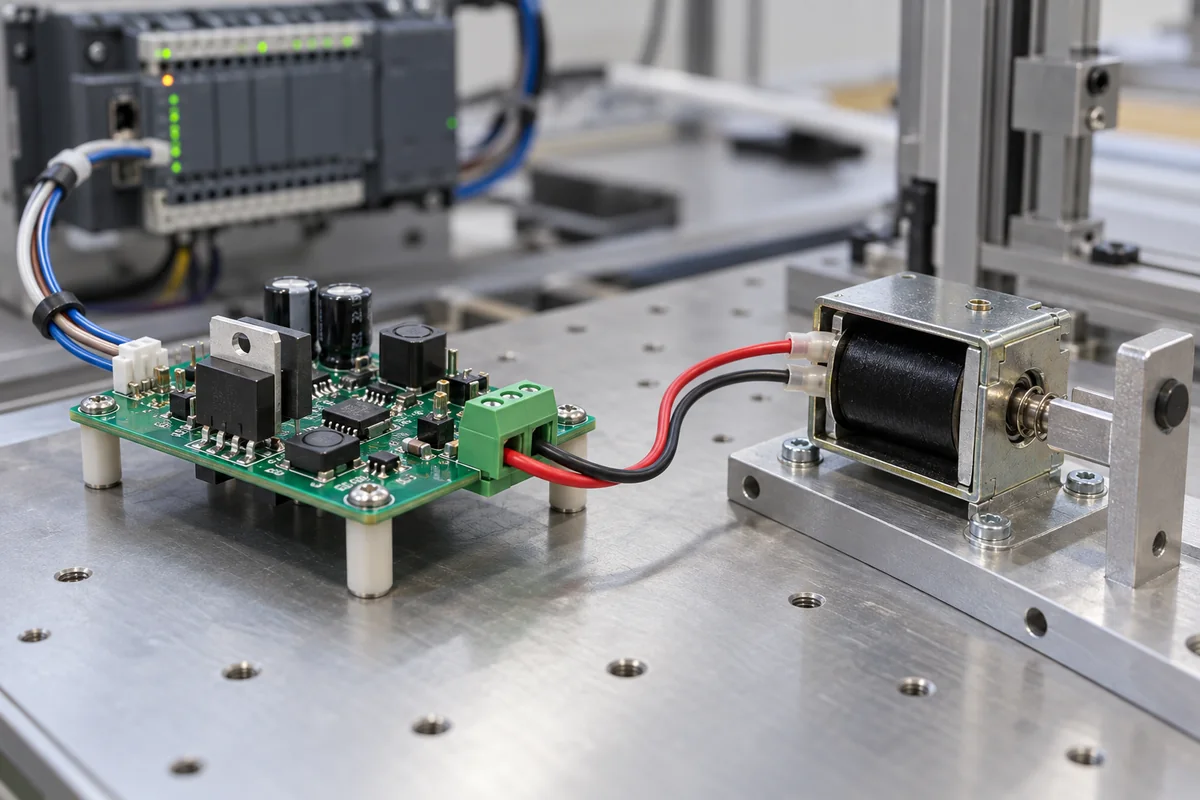
Representative product image. Confirm appearance and specifications with the manufacturer.

Product Specifications

Technical details and manufacturing context for Output Driver

Definition
An output driver is a critical electronic component within signal converters and transmitters that receives low-power control signals from processing circuits, amplifies them to appropriate voltage/current levels, and provides the necessary power and signal conditioning to reliably operate output devices such as actuators, relays, motors, or indicators. It serves as the interface between the control system and the physical output devices. The driver typically accepts digital or analog control signals from a microcontroller or signal processor. These signals are amplified through transistor arrays, operational amplifiers, or specialized driver ICs to provide sufficient power for the connected load. Protection circuits (overcurrent, overvoltage, thermal) are often integrated to ensure reliability. The driver may include isolation components (optocouplers, transformers) to separate control circuits from power circuits. Typical parameters include output current per channel (0.5–2.0 A), supply voltage (9–36 V DC), switching frequency (0–100 kHz), rise/fall time (10–50 ns at 1 kΩ load), operating temperature (-40–85 °C), storage temperature (-55–125 °C), input voltage level (3.3–5.0 V), output saturation voltage (0.2–0.5 V at rated current), leakage current (0.1–10 µA), ESD protection (±2–±8 kV, HBM model, per IEC 61000-4-2), and package type (SOP-8). Materials typically include semiconductor silicon, copper, epoxy resin, and ceramic substrate. These values are reference ranges and must be verified for the specific model and application. Always consult the legal manufacturer or supplier for exact specifications and compliance.
Working Principle
The output driver receives low-power control signals from a microcontroller or signal processor. These signals are amplified through transistor arrays, operational amplifiers, or specialized driver ICs to provide sufficient voltage and current for the connected load. Protection circuits such as overcurrent, overvoltage, and thermal shutdown are often integrated to ensure reliability. Isolation components like optocouplers or transformers may be used to separate control and power circuits. The driver conditions the signal to match the requirements of the output device, enabling reliable operation.
Common Materials
Semiconductor silicon, Copper, Epoxy resin, Ceramic substrate
Technical Parameters
ParameterTypical rangeNotes & selection driver
Output Current0.5–2.0 AContinuous current per channel
Supply Voltage9–36 V DCOperating range
Switching Frequency0–100 kHzMax PWM frequency
Rise Time10–50 nsAt 1 kΩ load
Fall Time10–50 nsAt 1 kΩ load
Operating Temperature-40–85 °CAmbient
Storage Temperature-55–125 °CNon-operating
Input Voltage Level3.3–5.0 VLogic high threshold
Output Saturation Voltage0.2–0.5 VAt rated current
Leakage Current0.1–10 µAOutput off state
ESD Protection±2–±8 kVHBM modelIEC 61000-4-2
Package TypeSOP-8Industry standard

Ranges are indicative industry figures for RFQ preparation, not a supplier commitment. Confirm every value and standard with the legal manufacturer before ordering.

Components / BOM
  • Power Transistor Part
    Amplifies control signals to drive high-current loads
    Material: Semiconductor silicon
  • Heat Sink Part
    Dissipates heat generated during operation
    Material: Aluminum alloy
  • Protection Circuit
    Prevents damage from overcurrent, overvoltage, and short circuits
    Material: Semiconductor components, resistors
  • Isolation Component
    Provides electrical isolation between control and power circuits
    Material: Optocoupler or transformer materials

Applied To / Applications

This component is essential for the following industrial systems and equipment:

Industrial Ecosystem & Supply Chain Structure

Complementary Systems
Downstream Applications
Specialized Tooling

Application Fit & Sizing Matrix

Operational Limits
current: Up to 2A continuous
voltage: 5V to 48V DC
temperature: -40°C to +85°C
frequency response: DC to 100kHz
Media Compatibility
✓ Industrial control systems ✓ PLC output modules ✓ Signal conditioning circuits
Unsuitable: High-voltage AC power distribution (>600V AC)
Sizing Data Required
  • Load current requirement (A)
  • Supply voltage range (V)
  • Switching frequency (Hz)

Reliability & Engineering Risk Analysis

Failure Mode & Root Cause
Bearing fatigue failure
Cause: Cyclic loading exceeding material endurance limit due to misalignment, imbalance, or improper lubrication leading to subsurface crack propagation
Shaft coupling wear
Cause: Misalignment-induced fretting corrosion and mechanical wear from angular/parallel offset exceeding coupling specifications
Maintenance Indicators
  • Abnormal high-frequency vibration (>4x baseline) with metallic ringing audible through stethoscope
  • Rapid temperature rise (>20°C above ambient) detected via infrared thermography on bearing housings
Engineering Tips
  • Implement laser shaft alignment during installation with ≤0.002 inch offset tolerance and quarterly verification
  • Establish condition-based lubrication using ultrasonic thickness monitoring to maintain optimal oil film thickness

Indicative industry ranges for design and RFQ preparation. Confirm the exact figures and applicable standard with the manufacturer before specifying.

Compliance & Manufacturing Standards

Applicable Standards
ISO 1940-1:2003 (Balance quality requirements for rotors) ANSI/ASME B46.1-2009 (Surface Texture) DIN 5480-1:2006 (Involute splines based on reference diameters)

Quoted from the published standard.

Manufacturing Precision
  • Bore diameter: +/-0.01mm
  • Surface flatness: 0.05mm per 100mm
Quality Inspection
  • Dimensional verification with CMM (Coordinate Measuring Machine)
  • Hardness testing (Rockwell C scale)

Manufacturers of Output Driver

Manufacturer profiles associated with Output Driver.

Sourcing Output Driver from China?
Tell us your specification and target quantity — we will match it against manufacturer records and come back with the factories that fit.
Request manufacturers We manufacture this

Manufacturer listings support early research and capability understanding. They are not certification, ranking, or transaction guarantees.

Technical documentation
Request current drawings, revision history, and a signed specification sheet.
Manufacturing capability
Verify equipment lists, process limits, capacity, and representative production evidence.
Inspection readiness
Confirm test methods, calibrated equipment, sampling plans, and traceable reports.
Supplier transparency
Check the legal entity, factory address, ownership, certifications, and direct contacts.

CNFX does not score or rank suppliers. Buyers must verify all claims and documents with the legal manufacturer before ordering.

Supply Chain Compatible Machinery & Devices

Industrial IoT Gateway

The Industrial IoT Gateway is a ruggedized edge computing device designed for industrial environments.

Explore Specs →
Modular Industrial Edge Computing Device

This modular industrial edge computing device is a ruggedized system designed for deployment in harsh industrial environments to perform real-time data processing, analytics, and control functions at the network edge.

Explore Specs →
Industrial Smart Camera Module

The Industrial Smart Camera Module is a compact, self-contained vision processing unit designed for integration into industrial machinery and production lines.

Explore Specs →
Surface Mount Resistor

Passive electronic component for current limiting and voltage division in circuits

Explore Specs →

Frequently Asked Questions

What is the typical output current range for an output driver?

The typical continuous current per channel is 0.5 to 2.0 A, but this is a reference range. The actual value depends on the specific model and application. Always check the datasheet or consult the manufacturer.

What supply voltage does an output driver require?

The operating supply voltage range is typically 9 to 36 V DC. However, this is a general reference. Verify the exact voltage requirements for your specific driver model.

Can an output driver handle PWM signals?

Yes, output drivers can handle PWM signals. The maximum switching frequency is typically up to 100 kHz. Confirm the frequency limits for your application with the manufacturer.

What ESD protection does an output driver have?

The ESD protection is typically ±2 to ±8 kV according to the HBM model, referenced to IEC 61000-4-2. This is a reference value; verify the actual rating for your specific part.

Data Basis

Editorial classification, named public sources where available, and source-reviewed manufacturer records.

Preliminary Technical Classification
This page supports structured research, RFQ preparation, and supplier evaluation. It does not replace buyer-led supplier qualification, standards review, or technical approval.
Buyer enquiry

Request manufacturing insight for Output Driver

Ask for use case, specification boundaries, supplier type, and RFQ preparation information for this product.

Where it goes
Straight to the CNFX editorial desk, and to the manufacturer if this product is linked to a claimed profile. Nothing is broadcast to a supplier list.
Your details stay here
We do not sell or rent enquiry data, and we do not add you to a mailing list. Used only to answer this request.
No commission, no middleman
CNFX is a directory. We take no cut of any order and never negotiate on a supplier's behalf.
What we don't claim
A listing is not an endorsement. Qualify every supplier and verify every figure yourself before ordering.

Your business information is used only to process this request.

Thank you! Your message has been sent. We'll respond within 1–3 business days.
Sorry, we couldn't send your message. Please try again, or email us at contact@cnfx.com.

Need to Manufacture Output Driver?

Compare manufacturer profiles with relevant product and process capability.

Previous Product
XY Positioning Stage
Last Product
Get QuotesChat