Radiation shielding housing for food X-ray inspection machines: leakage limits, tunnel curtains and shield doors, and lead thickness
The shielded cabinet around the X-ray tube and detector of a food inspection machine · the US limit of 0.5 mR/h at 5 cm, a 1 µSv design target, curtains and gap-closing doors at the product tunnels, and how much lead stops low-energy X-rays
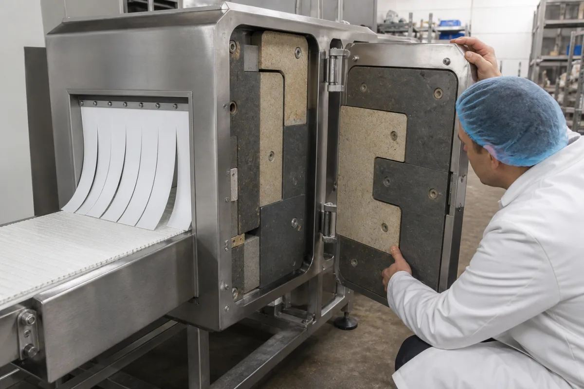
A food X-ray inspection machine is legally a cabinet X-ray system: the cabinet, not the room, has to hold the radiation in. The hard parts are the openings, because product has to go in and out on a conveyor while the tube is on, and the panels that are removed for cleaning. The housing is therefore judged by leakage measured outside it, by how the product tunnels are closed when no product fills them, and by interlocks on every panel and door.
The radiation-shielding cabinet of conveyor X-ray inspection machines for packaged and bulk food and beverages: shielded panels and doors, entry and exit tunnels, curtains and shield doors, interlocks and leakage surveys. Two-dimensional ionization chamber arrays for radiotherapy quality assurance are covered on the Ionization chamber arrays page; X-ray tubes and tube assemblies and flat-panel detectors have their own pages; shielded rooms for medical or industrial radiography are not covered here.
CNFX editorial research · Sources checked October 12, 2026 · 4 sources
0.5 mR/h at 5 cm from any surface, with every door and panel interlocked
Under 21 CFR 1020.40, a cabinet X-ray system, one whose enclosure contains the irradiated material, attenuates the radiation and excludes people while X-rays are generated, must meet these construction rules: [1]
Thermo Fisher Scientific designs its food X-ray machines so that no more than 1.0 µSv escapes at a minimum distance of 5 cm, which it describes as a worst-case combination of the US limit, which it gives as 5 µSv (0.5 mrem/h) at 5 cm, and the UK IRR 1999 figure of 1 µSv at 10 cm. It uses stainless steel or lead as interior shielding, requires a tool to open access panels, which are interlocked to stop the X-ray source and conveyor, and states that its machines emit 0.1 mrem per hour or less. [2] Editorial calculation: 0.1 mrem/h × 40 h × 50 weeks = 200 mrem a year, the worst-case added annual exposure Thermo Fisher gives for a worker at that emission rate.
Requirement
What the regulation says
Emission limit
No more than 0.5 milliroentgen in one hour at any point 5 cm outside the external surface, averaged over 10 cm² with no dimension over 5 cm [1]
Test condition
Tube potential, current, beam orientation and scatter set for maximum exposure; doors and panels closed and at any other position that allows X-rays [1]
Ports and apertures
No part of the body can reach the primary beam through a port, or enter through an aperture [1]
Doors
At least two safety interlocks, one of which physically disconnects the high-voltage generator supply on opening [1]
Access panels
At least one safety interlock; a separate control is needed to restart after any interlock trips [1]
Single faults
No single component failure may defeat more than one required interlock, or both X-ray-on indicators [1]
Ask for the factory leakage survey at the maximum tube voltage and current, with doors and panels at every position that allows X-rays, and for the survey to be repeated on site after installation.
02
Product tunnels: layered curtains, close-fitting tunnels and shield doors that close on a gap
Peco Controls' patent for an X-ray shielding structure for food inspection stations describes the usual enclosure around generator, product, sensor and conveyor, built from shielding material, with entry and exit tunnels dimensioned to fit closely around the containers so that a close-spaced line of containers fills them. [3]
The weakness it identifies is a gap: when a sizeable gap opens between containers, radiation escaping through the tunnels may become excessive. Its answer is two pairs of swinging shield doors of high-density shielding material, one pair in each tunnel, opened by pneumatic actuators under the inspection system's controller and closed when an infra-red sensor detects a gap reaching that tunnel; a release clutch and light spring loading close them passively if air or power fails, and the containers push them open. Its door actuators swing 90° from open to closed, or 180° for a station that can run in either direction. [3] It cites an earlier baggage-inspection system using four shielding curtains raised and lowered as each item passes. [3]
Thermo Fisher uses multiple layers of radiation-blocking curtains where products enter and exit, places warning signs on the in-feed and out-feed apertures, stops the X-rays whenever the belt stops for a jam, and advises customers to check curtains regularly and replace them as they wear. [2]
Give the supplier the largest pack and the gaps that can occur on the line, and ask whether tunnels rely on curtains, product fill or powered doors, and how they fail safe.
03
How much lead: attenuation of 50 to 100 keV photons per millimetre
NIST's tabulated mass attenuation coefficients for lead, with its density of 11.35 g/cm³, give the narrow-beam attenuation of a lead lining at the photon energies a low-voltage inspection tube produces: [4]
Editorial calculation: μ = μ/ρ × 11.35 g/cm³; half-value thickness = ln 2 ÷ μ; transmission = e^(−μ × 0.1 cm). These are narrow-beam figures without scatter build-up, for single energies; a tube emits a spectrum up to its peak voltage. Lead absorbs 80 keV photons less strongly than 100 keV ones because its K absorption edge lies at 88.0 keV, where NIST lists μ/ρ rising from 1.910 to 7.683 cm²/g. [4]
Editorial note: the regulation sets the leakage measured outside the cabinet, not a lead thickness, so lining thickness, overlaps at panel joints and the stepped edges of doors are proven by the leakage survey rather than by calculation alone. [1]
Ask for the maximum tube voltage, the lining material and thickness of each panel, door and curtain, and how joints between panels are overlapped.
04
What to state when buying or replacing an X-ray inspection housing
Paste it into your enquiry below or into an email to a maker, then replace every bracket.
X-ray source: [maximum tube voltage and current; number of tubes]
Product: [largest pack; container spacing; possible gaps]
Tunnels: [aperture size; curtains; powered shield doors; fail-safe]
Shielding: [panel material and thickness; joint overlaps]
Interlocks: [doors; access panels; key switch; belt-stop interlock]
Compliance: [21 CFR 1020.40 or local rule; leakage survey at factory and on site; registration]
Explore company information and manufacturing capabilities, then discuss the scope of your project with a relevant supplier.
Share this page
Compiled and source-reviewed by the CNFX editorial team.
Each manufacturer above links to the page on that company's own website where the product is listed, with the date we checked it. How we source and review
· Page last updated 13 October 2026
Buyer questions
What is the US leakage limit for a food X-ray inspection cabinet?
21 CFR 1020.40 limits emission to 0.5 milliroentgen in one hour at any point 5 cm outside the external surface. [1]
How many interlocks must a cabinet X-ray door have?
At least two, one of which physically disconnects the high-voltage generator supply when the door opens; each access panel needs at least one. [1]
What happens at the product tunnels when there is a gap in the line?
One Peco Controls design closes swinging shield doors in the tunnel when a sensor detects the gap, and lets them close passively if power fails. [3]
How much does 1 mm of lead attenuate 60 keV X-rays?
By editorial calculation from NIST coefficients, about 0.3 % of a narrow 60 keV beam passes 1 mm of lead. [4]
Sources and what still needs a direct check
Sources checked 2026-10-12. Construction rules come from the US federal performance standard for cabinet X-ray systems; design practice from a Thermo Fisher white paper on its food X-ray machines and a Peco Controls patent; lead attenuation from NIST's reference tables.