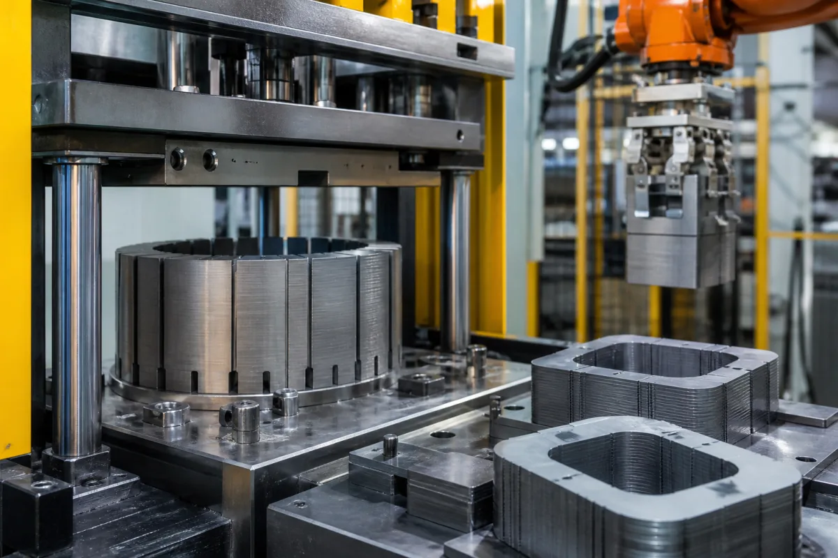
Electrical steel lamination core for transformers: stacked grain-oriented steel with step-lap joints
Stacked grain-oriented electrical steel cores for transformers · W17/50 grade limits, B8 induction and lamination factor, step-lap joints, building factor and no-load loss tolerance
This page covers stacked transformer cores built from grain-oriented electrical steel: laminations cut to length, stacked into limbs and yokes, and joined at the corners by step-lap joints. Ask three things first: which steel grade and thickness the core uses and how its loss was tested, how the joints are built (steps, laminations per step, overlap and gaps), and what building factor and no-load loss the supplier guarantees.
Stacked transformer cores and core laminations of grain-oriented electrical steel, including step-lap and mitred joint designs for distribution and power transformers. Motor and generator stator and rotor lamination stacks of non-oriented steel are covered on the Electric motor stator lamination stack page. Wound amorphous cores, complete transformers and steel coil supply alone are outside this page.
CNFX editorial research · Sources checked October 12, 2026 · 3 sources
Nippon Steel's ORIENTCORE table lists maximum iron loss W17/50 (1.7 T, 50 Hz), minimum induction B8 and minimum lamination factor by grade, at an assumed density of 7.65 kg/dm³. Conventional ORIENTCORE runs from 23Z110 (0.23 mm, ≤1.10 W/kg) to 35Z155 (0.35 mm, ≤1.55 W/kg) with B8 ≥1.80 T; ORIENTCORE HI-B from 20ZH80 (0.20 mm, ≤0.80 W/kg) to 35ZH135 with B8 ≥1.88 T; laser-irradiated HI-B·LS from 20ZDKH65 (0.20 mm, ≤0.65 W/kg) to 27ZDKH95; and HI-B·PM with refined magnetic domains from 20ZDMH70 to 23ZDMH90 with B8 ≥1.87 T. Lamination factors rise with thickness, from ≥94.0% at 0.20 mm to ≥96.0% at 0.35 mm. [1]
The test basis differs: Nippon Steel measures ORIENTCORE, HI-B and HI-B·PM to JIS C 2550:2000 on longitudinal specimens after stress-relief annealing, but HI-B·LS to JIS C 2556:2015 on as-sheared single-sheet samples without stress-relief annealing, and it maps its grades to JIS C 2553, IEC 60404-8-7 and GB/T 2521 limits. [1]
Editorial calculation: 23ZDKH70 at ≤0.70 W/kg carries about 42% less specific loss than conventional 27Z120 at ≤1.20 W/kg (0.70 ÷ 1.20 ≈ 0.58), before the building factor of the finished core. [1]
Give the supplier the transformer rating, design induction, target no-load loss and exciting current, core type (three-limb, five-limb, shell), limb diameter and window size, preferred steel grades and the loss tolerance you will accept.
02
Plan the joints, building factor and no-load loss
Aleksandar Lojpur, former head of electrical design at Končar Power Transformers, gives no-load loss as P0 = GFE · p0 · KB: core weight times the Epstein specific loss at the working frequency and induction times a building factor that depends on core dimensions (the weight of the corners) and core type, with step-lap (5–7 standard), the number of layers per step (1–2 standard) and the gap in the joints as further influences. He notes that at the corner joints the flux is not along the grain, so better-oriented steel has a higher building factor, and that IEC 60076-1 allows +15% and IEEE C57.12.00 +10% on guaranteed no-load loss. [2]
His worked example for one large core at 0.915 filling factor gives 89,845 kg of core and 118.3 kW of no-load loss at 1.67 T, against 83,911 kg and 138.9 kW at 1.77 T; at 1.10 times rated voltage the loss rises to 174.3 kW and 212.0 kW. [2] Editorial calculation: raising design induction from 1.67 to 1.77 T saves about 6.6% of core mass but raises no-load loss about 17%, from about 1.32 to 1.66 W/kg of core. [2]
A 2010 IET Electric Power Applications paper by Hernández, de León, Cañedo and Olivares-Galván modelled flux in wound and step-lap stacked core joints with Gaussian fits from 2D and 3D finite-element simulations for grain-oriented and super grain-oriented steel; it states that air-gap length, overlap length, number of laminations per step and material quality have significant effects on core losses, and that its models differ from finite-element results by under 6%. [3]
03
ORIENTCORE conventional, HI-B, laser and HI-B·PM grade families
All values are maximum W17/50 and minimum B8 from one producer's table.
Explore company information and manufacturing capabilities, then discuss the scope of your project with a relevant supplier.
Share this page
Compiled and source-reviewed by the CNFX editorial team.
Each manufacturer above links to the page on that company's own website where the product is listed, with the date we checked it. How we source and review
· Page last updated 13 October 2026
Buyer questions
What do grain-oriented steel grade names like 23ZH85 mean?
In Nippon Steel's table 23ZH85 is 0.23 mm ORIENTCORE HI-B with W17/50 ≤0.85 W/kg and B8 ≥1.88 T. [1]
How is transformer no-load loss estimated from the steel?
As core weight × specific loss × building factor; the building factor depends on core dimensions, type and joint design. [2]
What tolerance applies to guaranteed no-load loss?
IEC 60076-1 allows +15% and IEEE C57.12.00 +10%, as summarised in Lojpur's transformer core lesson. [2]
Sources and what still needs a direct check
Sources checked 2026-10-12. Nippon Steel publishes its own grade limits; the transformer core lesson is a designer's teaching material published by Transformers Magazine; the IET paper is a peer-reviewed modelling study.