Redundant Power Supply
View system integration details
This page explains how Hot-Swap Connector is classified within Electrical Equipment Manufacturing. Technical values and manufacturer relationships are research references; confirm the current specification and supplier evidence for each order.
Electrical connector designed to be safely connected or disconnected while equipment is powered on
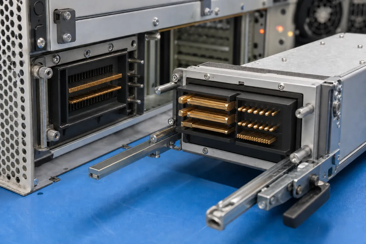
Technical details and manufacturing context for Hot-Swap Connector
| Parameter | Typical range | Notes & selection driver |
|---|---|---|
| Rated Current | 5–30 A | Derating above 30 A requires forced coolingIEC 60512-5-2 |
| Rated Voltage | 250 V AC | Max continuous AC voltageIEC 60512-5-1 |
| Contact Resistance | ≤20 mΩ | Initial resistance at rated currentIEC 60512-2-1 |
| Insulation Resistance | ≥1000 MΩ | At 500 V DCIEC 60512-3-1 |
| Dielectric Withstanding Voltage | 1500 V AC | For 1 minute, no breakdownIEC 60512-4-1 |
| Operating Temperature | -40–85 °C | Extended range available on requestIEC 60068-2-14 |
| Mating Cycles | 500–1000 cycles | Contact resistance may increase after 500 cyclesIEC 60512-9-1 |
| IP Rating | IP54–IP65 | IP65 requires mated conditionIEC 60529 |
| Contact Plating | 0.76–1.27 μm Au | Gold over nickel, for corrosion resistanceASTM B488 |
| Housing Material | PA66+30%GF | Flame retardant, halogen-freeUL 94 V-0 |
| Weight | 15–60 g | Depends on number of contacts |
Ranges are indicative industry figures for RFQ preparation, not a supplier commitment. Confirm every value and standard with the legal manufacturer before ordering.
This component is essential for the following industrial systems and equipment:
| current: | Up to 50A per contact |
| voltage: | Up to 600V AC/DC |
| temperature: | -40°C to +125°C |
| mating cycles: | ≥500 cycles |
| dielectric withstand: | 1500V AC for 60 seconds |
| insulation resistance: | ≥1000 MΩ |
Indicative industry ranges for design and RFQ preparation. Confirm the exact figures and applicable standard with the manufacturer before specifying.
Quoted from the published standard.
1 company lists this product among what they make. Company figures are quoted from each company's own website; every card states where the relationship came from.
Manufacturer listings support early research and capability understanding. They are not certification, ranking, or transaction guarantees.
A practical evidence checklist for RFQ preparation and supplier evaluation.
CNFX does not score or rank suppliers. Buyers must verify all claims and documents with the legal manufacturer before ordering.
Staggered pin lengths ensure that ground connections are made first and broken last during insertion and removal. This prevents electrical arcing and system damage by establishing a safe ground path before power and signal pins connect.
The rated current is 5–30 A, with derating required above 30 A. For currents above 30 A, forced cooling is necessary. Always verify the specific model's current rating with the manufacturer.
The connector references standards such as IEC 60512-5-2 for rated current, IEC 60512-5-1 for rated voltage, and IEC 60512-2-1 for contact resistance. These standards are for verification and procurement; they do not guarantee certification. Confirm compliance with the supplier.
The IP rating ranges from IP54 to IP65, with IP65 requiring a mated condition. IP65 provides protection against dust and water jets, but for outdoor use, consider additional environmental factors. Verify the exact IP rating for your model.
Editorial classification, named public sources where available, and source-reviewed manufacturer records.
Ask for use case, specification boundaries, supplier type, and RFQ preparation information for this product.
Compare manufacturer profiles with relevant product and process capability.