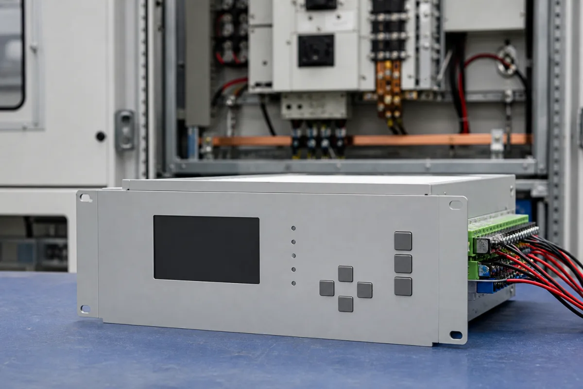
A protection relay measures current, and for some functions voltage, from instrument transformers and opens a circuit-breaker through its output contacts when it detects an overcurrent, earth fault or other abnormal condition. Ask three things first: which inverse-time curves and setting ranges it offers, what current transformers it needs to measure faults correctly, and how fast and how accurately it operates so that relays in series can be graded.
Numerical (digital, microprocessor) protection relays for feeders, motors and distribution lines. Relay test sets, general-purpose and time relays, relay sockets, DIN-rail voltage protectors and thermal overload relays are outside this page.
CNFX editorial research · Sources checked October 12, 2026 · 4 sources
Read the inverse-time (IDMT) curve the relay applies
ABB's 615-series technical manual explains that in inverse-time modes the higher the current, the faster the relay operates, and that operate time is t[s] = (A / ((I/I>)^C − 1) + B) · k, where I is the measured current, I> the set start value and k the time multiplier. Its coefficients include IEC Normal Inverse A = 0.14, B = 0, C = 0.02; IEC Very Inverse 13.5, 0, 1.0; IEC Extremely Inverse 80.0, 0, 2.0; and ANSI Very Inverse 19.61, 0.491, 2.0. [1]
Editorial calculation with ABB's formula and coefficients, at time multiplier k = 0.1: at twice the start value, IEC Normal Inverse operates in about 1.00 s, Very Inverse in 1.35 s and Extremely Inverse in 2.67 s; at ten times the start value the order reverses, to about 0.30 s, 0.15 s and 0.081 s. A steeper curve therefore waits longer on small overloads and clears heavy faults faster. [1]
The manual describes two ways to level out the curve at high currents: a minimum operate time, or an IDMT saturation point set as a multiple of the start value (default 50). It warns that IDMT operation above 50 × In is not guaranteed, so with a start value of 2.5 × In the curve levels out at 50/2.5 = 20 × I/I>. [1]
In ABB's REF615 product guide, the low stage start value ranges 0.05–5.00 × In, the time multiplier 0.05–15.00 and the operate delay 40–200000 ms, with a choice of definite or inverse time curves. [3] Editorial note: ask each supplier for its curve equation and coefficients, because curve names alone do not guarantee identical operate times across makes.
Give the supplier the protected object (feeder, motor, transformer, line), CT and VT ratios, the protection functions needed, curve types and setting ranges, auxiliary supply voltage, the number of binary inputs and trip outputs, communication protocol, mounting and case size, and the type-test standards required.
02
Match the current transformers to the relay
ABB's REF615 application manual explains that a saturated CT distorts the secondary current and may endanger operation and selectivity. It quotes IEC 60044-1 protective classes: 5P allows 5% composite error at the rated accuracy limit primary current and 10P allows 10%, and both suit non-directional overcurrent protection. The actual accuracy limit factor Fa ≈ Fn × |Sin + Sn| / |Sin + S| changes with the connected burden S. [2]
For non-directional overcurrent protection ABB recommends a CT with Fa of at least 20, a nominal primary current I1n > Ikmax/100 so the relay input is not overstressed, a start setting below 0.7 × (Ikmin/I1n), and, for inverse-time stages without high-set stages, Fa > 20 × start value/I1n. Its worked feeder has 41.7 kA maximum and 22.8 kA minimum fault current and a CT with an actual Fa of 59. [2]
Editorial calculation: with ABB's 41.7 kA example, I1n > 41,700/100 = 417 A, although ABB notes that CT saturation protects the relay input, so a few times smaller I1n can be used in practice. [2] The REF615 1/5 A current inputs withstand 20 A continuously and 500 A for 1 s. [3]
03
Check speed and accuracy before grading relays
ABB's technical manual states that a 150 ms grading margin in definite-time mode can be used provided the circuit-breaker interrupting time is shorter than 60 ms, because numerical units allow some CT saturation, operate accurately and have short retardation times. [1]
The REF615 product guide lists, for its non-directional overcurrent stages, operation accuracy of ±1.5% of the set value or ±0.002 × In, a reset ratio of 0.96 (typ.), retardation time below 40 ms, and operate time accuracy of ±1.0% of the set value or ±20 ms in definite-time mode and ±5.0% of the theoretical value or ±20 ms in inverse-time mode. [3]
Editorial note: build the grading margin from the breaker interrupting time, the relay's timing error and retardation, and a safety allowance, and ask each supplier for these figures for the exact function and output contact used.
04
Hardware options to settle before ordering
Listings range from microcomputer feeder protection relays and recloser controllers to low-voltage motor and distribution-line protection relays; ask each for its curve equations, setting ranges and type-test reports.
A second maker's feeder relay shows which hardware options to fix in the order. Schweitzer Engineering Laboratories lists for its SEL-751 an operating range of −40 to +85 °C, power supply options of 110–250 V DC/110–240 V AC or 24–48 V DC, an optional 200 mA sensitive neutral input for ground faults on high-impedance grounded, ungrounded and Petersen-coil systems, a low-energy analog (LEA) card with three Rogowski-coil or low-power current inputs, three LEA voltage inputs and the 200 mA neutral, and an option card with two AC voltage inputs (300 V, or 8 V LEA, plus Vbat) and four arc-flash detection inputs. Up to four extended I/O modules can be added, each with 21 programmable inputs or 12 contact outputs; the front panel is a 5-inch, 800 × 480 capacitive touchscreen; IEEE C37.118 synchrophasors run at up to 60 messages per second and SNTP time sync gives 1 ms accuracy. SEL states ATEX and UL Class I, Division 2 certification and a conformal-coating option. [4]
Editorial note: the SEL-751 and REF615 both offer conventional 1/5 A CT inputs and sensor-input variants, so state in the enquiry whether the switchgear uses conventional CTs and VTs or Rogowski coils and LEA voltage sensors, which auxiliary supply (DC battery voltage or AC) is available, and how many binary inputs and outputs the scheme needs. [4][3]
05
Inside a REF615: inputs, outputs and supply
The rows follow ABB's REF615 product guide; other makes arrange inputs, outputs and supply differently.
Part
Role
Fix in the order
Current inputs
1 A or 5 A CT inputs; 20 A continuous, 500 A for 1 s. [3]
Huayi lists HYP-series microcomputer protection relays with a feeder terminal unit and recloser controller; Blue Jay lists low-voltage motor protection and distribution-line protection relays.
Huayi Electric Co., Ltd.
Manufacturing site to be confirmed for the order
Lists HYP-series microcomputer protection relays with a feeder terminal unit and recloser controller.
Explore company information and manufacturing capabilities, then discuss the scope of your project with a relevant supplier.
Share this page
Compiled and source-reviewed by the CNFX editorial team.
Each manufacturer above links to the page on that company's own website where the product is listed, with the date we checked it. How we source and review
· Page last updated 13 October 2026
Buyer questions
How does an inverse-time protection relay calculate trip time?
ABB's 615-series manual uses t = (A/((I/I>)^C − 1) + B) · k with IEC or ANSI coefficients, so higher current gives faster operation. [1]
What CT accuracy limit factor does a protection relay need?
For non-directional overcurrent protection ABB recommends a CT with an actual accuracy limit factor of at least 20 and gives formulas tied to the start setting. [2]
What grading margin can numerical relays use?
ABB states a 150 ms definite-time margin can be used if the breaker interrupts in under 60 ms. [1]
What auxiliary supply does a numerical feeder relay need?
It is chosen at order: SEL lists 110–250 V DC/110–240 V AC or 24–48 V DC power supply options for the SEL-751. [4]
Sources and what still needs a direct check
Sources checked 2026-10-12. Three sources are ABB documents for its own 615-series relays and one is SEL's product page for its SEL-751; they illustrate how makers define curves, CT requirements and ratings. Values for another relay must come from its own manual and type tests.