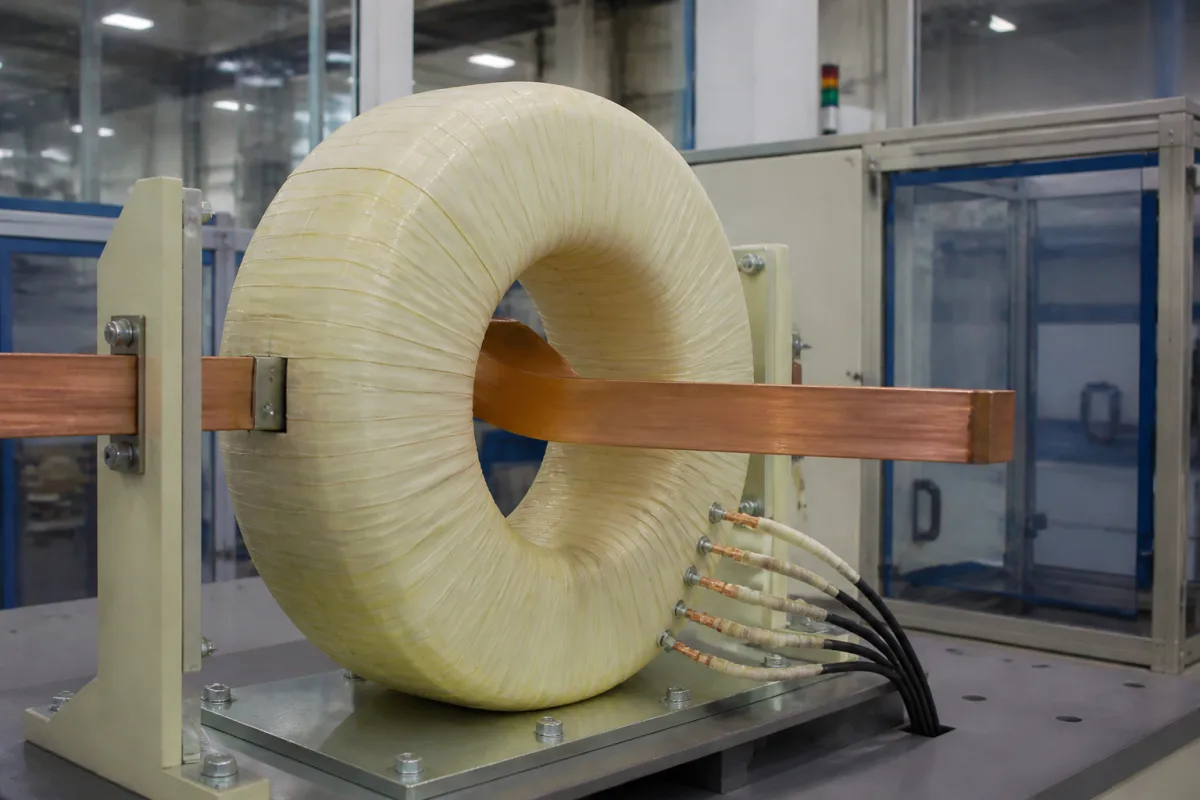
Instrument transformers · Ratio, class, burden and safe wiring
A current transformer is only as accurate as the circuit it drives. Metering CTs must be precise at normal load; protection CTs must stay linear during a fault current that is a multiple of rated current. Choose the class for the job, add up the real burden of meters, relays and leads, and wire the secondary so it can never be opened while the primary carries current.
Low- and medium-voltage current transformers for metering, protection and monitoring: window, bar-type, wound and split-core designs, cast-resin and oil-immersed. Voltage transformers and electronic current sensors are outside this page.
CNFX editorial research · Sources checked October 12, 2026 · 5 sources
ABB's instrument transformer guide explains that metering transformers need high accuracy at normal operating current, while protection transformers need linearity over a wide range so relays see faults correctly. For CTs, ABB states that "typical output levels of instrument transformers are 1-5 amperes". [1]
Under IEEE C57.13, as ABB summarises it, metering classes 0.3, 0.6 and 1.2 set the permitted ratio and phase-angle error at a stated burden; twice the error is allowed at 10% of rated current, and the 100% limit applies up to the current allowed by the thermal rating factor, which ABB describes as "a multiplier of 1.5 or 4.0 applied to many transformers". [1]
For relaying, ABB explains C and T classes based on a 10% error limit from 1 to 20 times rated current. The number is the secondary voltage the CT can deliver without saturating: a C200 CT can drive 100 A (20 × 5 A) into a 2 Ω burden, 200 V, within 10% error. ABB lists standard relaying classes of 50, 100, 200 and 800. [1]
Suppliers selling to IEC markets quote classes such as 0.2S or 0.5S; GFUVE, for example, lists a 2000/5 A medium-voltage CT in class 0.2S or 0.5S. IEC 61869-2 was not read for this page, so ask the supplier which standard each class refers to. [2]
Tell the supplier what the CT feeds: revenue meter, panel meter, protection relay or monitoring device. One core rarely does both metering and protection well; ask whether a multi-core CT is offered.
02
Add up the real burden of the secondary circuit
ABB notes that CT accuracy holds only at the burden it is rated for, and that the test burden must include the secondary leads. IEEE C57.13 standard burdens for 5 A secondaries run from B-0.1 (2.5 VA) to B-1.8 (45 VA) for metering and B-1 (25 VA) to B-8 (200 VA) for relaying; for other secondary ratings the ohmic values scale by (5/I)². [1]
As an editorial calculation example only: a lead loop of 0.7 Ω carrying 5 A absorbs 0.7 × 5² ≈ 17.5 VA, more than a B-0.5 metering burden of 12.5 VA on its own; at a 1 A secondary the same loop absorbs only 0.7 VA. Long lead runs are one reason to specify 1 A secondaries.
List every device on the secondary with its burden, plus the cable length and cross-section, and ask the supplier to confirm the class at that total burden.
03
Never open a loaded secondary
ABB explains that if the secondary is opened while primary current flows, all of it becomes exciting current, producing very high voltage peaks at the secondary terminals as the current passes through zero. These peaks may not show on an ordinary voltmeter but can break down insulation and are dangerous to personnel; ABB treats an open secondary as a serious accident. [1]
ABB states CTs are insulated for emergency secondary peaks up to 3,500 V; for larger CTs where opening is probable, a protective device should be permanently connected across the secondary. An open circuit or a fault can also leave the core magnetised, which affects later accuracy. [1]
Specify shorting terminal blocks so meters and relays can be removed safely, and ground the secondary at one point; ABB notes that "grounding of the secondary circuit is most important, but in complicated three-phase connections, the best point to ground is not always easily determined". [1]
04
Check thermal rating and short-circuit withstand
ABB describes the continuous thermal current rating factor as a multiplier of rated current the CT can carry continuously at 30 °C ambient, and gives a loading guide for 55 °C rise CTs: loading to that guide is not safe if average ambient exceeds 30 °C or overloads occur more than once a day. [1]
Ask for the rated short-time thermal current and dynamic (peak) current against your prospective fault level, and the insulation level for the system voltage. Lugao, for example, lists oil-immersed CTs up to 330 kV and epoxy-cast ring CTs for low voltage. [3]
05
Window, busbar, cast-resin, oil-immersed and split-core builds
HEAG, Lugao and GFUVE between them list low-voltage window and busbar CTs, medium-voltage cast-resin CTs, oil-immersed high-voltage CTs, zero-sequence CTs and split-core CTs. [4][3][2]
HEAG, for example, lists 0.66 kV indoor CTs and cast-resin instrument transformers from 3 to 36 kV; CNC Electric lists RCT indoor CTs for circuits up to 0.5 kV at 50 Hz. [4][5]
06
Core, windings, insulation and terminals
Materials come from the data sheet of the CT you order.
Part
Role
Fix in the order
Core
Carries the flux; saturation sets relaying class. [1]
Core material, number of cores and knee point or class.
Primary conductor or winding
Busbar, cable through the window or wound primary.
Paste it into your enquiry below or into an email to a maker, then replace every bracket.
Circuit: [system voltage; frequency; normal and maximum load current; fault level]
Use: [revenue metering; panel metering; protection relay; monitoring]
Ratio: [primary/secondary; multi-ratio taps; number of cores]
Class: [per core; standard (IEEE or IEC)]
Burden: [devices and VA; lead length and cross-section]
Mounting: [window size; busbar or cable; indoor or outdoor; split-core]
Ratings: [short-time thermal current; dynamic current; insulation level; thermal rating factor]
Documents: [routine test report; accuracy test at stated burden; type test certificates]
12 companies list this product among what they make. Company figures are quoted from each
company's own website; every card states where the relationship came from.
Huayi Electric Co., Ltd.
Manufacturing site to be confirmed for the order
Lists 0.66 kV indoor CTs, cast-resin instrument transformers from 3 to 36 kV, zero-sequence and oil-immersed CTs.
Explore company information and manufacturing capabilities, then discuss the scope of your project with a relevant supplier.
Share this page
Compiled and source-reviewed by the CNFX editorial team.
Each manufacturer above links to the page on that company's own website where the product is listed, with the date we checked it. How we source and review
· Page last updated 13 October 2026
Buyer questions
What happens if a CT secondary is opened under load?
ABB explains that all primary current becomes exciting current, producing very high voltage peaks that can break down insulation and endanger personnel. Short the secondary before removing any device. [1]
What does C200 mean?
Under IEEE C57.13, as ABB explains, the CT can deliver 200 V at 20 times rated secondary current (100 A for 5 A) into a 2 Ω burden within 10% error. [1]
Why does burden matter?
ABB notes CT accuracy is specified at a stated burden, including leads; a higher real burden can push a metering CT out of class or saturate a protection CT. [1]
Sources and what still needs a direct check
Sources checked 2026-10-12. ABB is an instrument transformer manufacturer; its guide explains IEEE C57.13 classes and practice. Supplier pages describe their own offers. IEEE C57.13 and IEC 61869-2 were not read for this page.