Diode bridge rectifiers and rectifier stacks · repetitive peak reverse voltage against mains voltage, average output current with heatsink or PCB mounting, surge current and I²t for fusing, forward voltage and losses, case insulation and mounting torque
A bridge rectifier (or rectifier stack) is an assembly of diodes that converts AC into DC: in a single-phase full-wave bridge, four diodes steer each half-cycle to the DC output, so two diodes conduct at any time; larger stacks combine diodes and heatsinks for high-current power supplies. Ask three things first: what reverse voltage the diodes must block for your AC input, what average and surge current they must carry with your cooling, and how the assembly is insulated and mounted.
Single-phase and three-phase diode bridge rectifiers and diode rectifier stacks with heatsinks for AC/DC power supplies, from PCB-mount bridges to cabinet-mounted assemblies. Thyristor-controlled rectifiers, Schottky and fast-recovery diodes sold as individual parts, and complete DC power supplies are outside this page except where compared.
CNFX editorial research · Sources checked October 11, 2026 · 4 sources
Vishay's GBU8 data sheet for glass-passivated single-phase bridge rectifiers, used for AC/DC full-wave rectification in power supplies, adapters and appliances, lists repetitive peak reverse voltage (V_RRM) options of 50, 100, 200, 400, 600, 800 and 1,000 V with corresponding maximum RMS input voltages of 35, 70, 140, 280, 420, 560 and 700 V. The average rectified output current is 8.0 A at a case temperature of 60 °C when the bridge is mounted on an aluminium plate heatsink, but only 3.9 A at 40 °C ambient when mounted on a PCB in free air with 12 × 12 mm copper pads; the recommended mounting is bolted to a heatsink with silicone thermal compound. [1]
Editorial calculation: a 230 V rms mains input peaks at about 230 × √2 ≈ 325 V. In this family the lowest grade whose maximum RMS rating covers 230 V is the 400 V V_RRM part (280 V rms), and a higher grade gives more margin for line surges. The mains voltage is an assumed example; check transient conditions on your supply.
Give the supplier the AC input (single- or three-phase, voltage, frequency, transients), DC output current (average and peak), load type (resistive, capacitive, inductive), surge and inrush conditions, fusing, cooling (PCB, heatsink, forced air), insulation requirements, mounting and terminals, and for stacks the busbar, enclosure and protection (snubbers, fuses) arrangement.
02
Check surge rating, losses and mounting
The same data sheet gives a peak non-repetitive forward surge current of 200 A (single sine wave superimposed on rated load), an I²t fusing rating of 166 A²s for t < 8.3 ms, a maximum forward voltage of 1.0 V per diode at 8.0 A, reverse current of 5 µA at 25 °C rising to 500 µA at 125 °C at rated voltage, operation from −55 to +150 °C, a case dielectric strength of 1,500 V rms, a UL 94 V-0 molding compound and a maximum mounting torque of 10 cm·kg (recommended 5.7 cm·kg). [1]
Micro Commercial Components (MCC) publishes the same GBU8 part numbers with different test conditions: 8.0 A average at a 100 °C case temperature on a 75 × 45 × 5.5 mm aluminium heatsink, 220 A peak surge for 8.3 ms, a maximum forward voltage of 1.0 V at 4 A and 1.2 V at 8 A, 200 A²s I²t and a typical junction-to-case thermal resistance of 2.2 °C/W. [2] Editorial note: the same part number from two makers is stated under different conditions, so compare data sheets line by line rather than by part number.
Editorial calculation: in a single-phase bridge two diodes conduct at a time, so at 8 A the forward-voltage loss is at most about 2 × 1.0 V × 8 A = 16 W, which the heatsink must remove. This is an upper-bound estimate from the maximum forward voltage; ask the supplier for loss curves at your current and temperature.
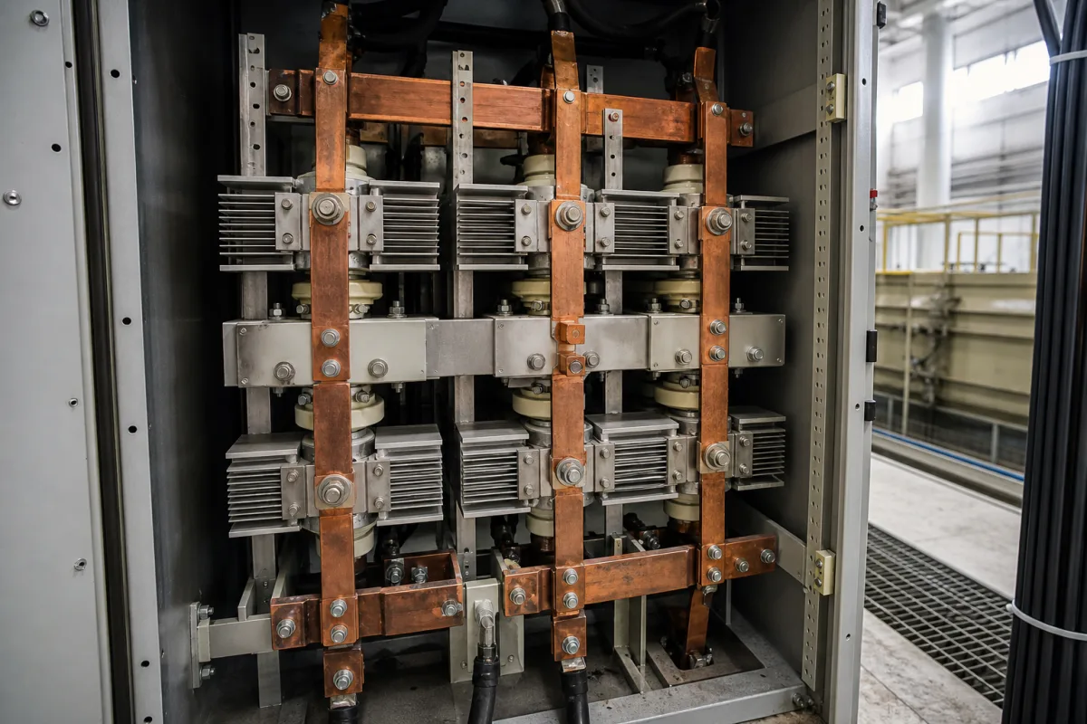
Editorial note: high-current rectifier stacks use larger diodes clamped between heatsinks and copper busbars; ask for the device ratings, clamping force, heatsink thermal resistance and cooling airflow, as well as the same reverse-voltage, surge and I²t data.
03
Compare rectifier forms
No manufacturer record has been reviewed for this product yet; the forms below come from the source cited and the definition of this product.
Forms range from single-phase in-line bridges for PCB or heatsink mounting, such as the GBU package, to cabinet-mounted rectifier stacks of diodes, heatsinks and busbars for high-current DC supplies. [1]
04
Read a three-phase bridge data sheet before you specify one
For three-phase input, Vishay's VS-36MT series data sheet describes an encapsulated three-phase bridge in the D-63 package with an electrically insulated case and centre-hole fixing. It rates 35 A maximum DC output current at a 60 °C case temperature for 120° rectangular conduction, with repetitive peak reverse voltage grades from 50 to 1600 V; each grade also has a higher non-repetitive limit, for example 1300 V for the 1200 V grade. [3] The one-cycle surge rating is 475 A at 10 ms and 500 A at 8.3 ms with no voltage reapplied, falling to 400 A at 10 ms when 100% of V_RRM is reapplied; I²t for fusing is 1130 A²s at 10 ms, or 800 A²s with voltage reapplied. [3]
The same data sheet gives a maximum forward drop of 1.19 V per junction at 40 A peak and 25 °C, reverse current of 100 µA per junction at rated voltage and 25 °C, an RMS isolation test of 2700 V for 1 s at 50 Hz with all terminals shorted, thermal resistance of 1.35 K/W junction to case per bridge and 0.2 K/W case to heatsink on a smooth, flat, greased surface, and a mounting torque of 2.0 Nm ±10% with an M4 screw. [3] Editorial calculation: 1.35 + 0.2 = 1.55 K/W from junction to heatsink, so the heatsink thermal resistance you choose sets the remaining margin to the 150 °C junction limit. [3] Editorial note: when a fuse protects the bridge, compare the fuse's let-through I²t with the reapplied-voltage figure, not only the no-voltage figure.
05
Apply a derating margin to the data-sheet ratings
NASA Goddard's EEE-INST-002, written for parts on its space flight projects, derates diodes by multiplying each stress parameter by a factor. Its Table 4 sets, for general purpose, rectifier, switching, PIN/Schottky diodes and thyristors, 0.70 for peak inverse voltage (PIV), 0.50 for surge current, forward current and power, and 0.80 for maximum junction temperature, never above 125 °C or 40 °C below the maximum rating, whichever is lower. [4]
Editorial calculation: a 230 V rms mains input peaks at about 325 V, and 325 ÷ 0.70 ≈ 464 V, so under this factor the 600 V grade is the lowest GBU8 grade that fits, one step above the 400 V grade chosen earlier on RMS rating alone. [1][4] Editorial note: these are NASA's space flight rules, not a commercial requirement; agree which margin your design applies, then give the supplier the derated values you need.
Fill the specification fields with values for your supply
A rectifier quotation needs values for your supply. The table explains each field, gives published values where a reviewed source states them, and says what to obtain from the supplier.
Explore company information and manufacturing capabilities, then discuss the scope of your project with a relevant supplier.
Share this page
Compiled and source-reviewed by the CNFX editorial team.
Published product pages show what a company offers, not tested performance. Confirm the legal seller, factory and scope for your order. How we source and review
· Page last updated 13 October 2026
Buyer questions
What voltage rating does a bridge rectifier need?
Choose a grade whose maximum RMS rating covers your AC input with margin; Vishay's GBU8 range runs from 35 to 700 V rms (50–1,000 V V_RRM). [1]
Why does a bridge's current rating depend on mounting?
Cooling limits it: the GBU8 carries 8 A on an aluminium heatsink but 3.9 A on a PCB in free air. [1]
How much power does a bridge rectifier lose?
Roughly two diode drops times the current; at 8 A and 1.0 V per diode, up to about 16 W. [1]
What surge current can a 35 A three-phase bridge rectifier take?
Vishay's VS-36MT data sheet gives 475 A for one 10 ms cycle with no voltage reapplied, and 400 A when 100% of the rated reverse voltage is reapplied. [3]
How much margin should a bridge rectifier's ratings have?
NASA Goddard's EEE-INST-002 applies factors of 0.70 to a rectifier diode's peak inverse voltage and 0.50 to its surge and forward current, and keeps the junction below 125 °C or 40 °C under the maximum rating, whichever is lower. [4]
Sources and what still needs a direct check
Sources checked 2026-10-11. Vishay General Semiconductor and Micro Commercial Components describe their own GBU8 bridge rectifiers; their figures illustrate how ratings are stated, not limits for other products.