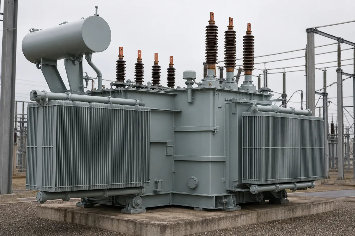
Step-up transformer for power stations: the generator step-up (GSU) unit between generator and grid
Generator step-up (GSU) transformers at power stations · generator-voltage to transmission-voltage ratios, volts-per-hertz overexcitation, vector group and low-voltage options, weight, transport and spare units
A step-up transformer at a power station, the generator step-up (GSU) transformer, takes the generator's output at a few tens of kilovolts and raises it to the transmission voltage of the grid it feeds. Unlike a distribution transformer it is loaded close to its rating whenever the plant runs, it is exposed to the generator's own voltage and frequency excursions, and if it fails the plant cannot export. Buyers therefore ask about the voltage ratio and vector group, its tolerance to overexcitation, its weight and transport, and how a spare would be found.
Generator step-up transformers that connect power station generators to transmission networks: three-phase units and banks of single-phase units, their voltage ratios, vector groups, overexcitation (volts-per-hertz) duty, size, transport and spare strategy. Distribution and network power transformers, with their loss classes, cooling classes and insulation life, are covered on the Power transformer page; converter transformers for 12-pulse DC supplies on the Rectifier main transformer page. Low-voltage step-up transformers for equipment supplies (for example 220 V to 380 V) and high-frequency electronic transformers are outside this page.
CNFX editorial research · Sources checked October 12, 2026 · 4 sources
Ratios, MVA and weight: what a GSU between 13.8 kV and 765 kV looks like
The US Department of Energy's 2012 study of large power transformers defines generation step-up transformers in its large class as units with a high-voltage side of 100 kV or more and a maximum nameplate rating of 75 MVA or more, and gives approximate sizes for 2011. [1]
DOE notes that its prices are FOB factory, exclude transport, oil, installation and special testing such as short-circuit tests, and that total installed cost is estimated at about 25–30 percent higher. In 2010 the average lead time from order to delivery was five to 12 months from US producers and six to 16 months from producers outside the United States, and could extend beyond 20 months and up to five years in extreme cases. [1]
At the top of the range, Hitachi Energy tested the first of six single-phase shell-form GSUs rated 700 MVA at 420/27 kV for a power plant of about 1.8 GW; the three units of one bank weigh around 1,200 tons, about 400 tons each. Hitachi describes the GSU as continuously in operation at almost full load and subject to dielectric, thermal and mechanical stresses, including network short-circuit faults. [4] Editorial calculation: 420 ÷ 27 ≈ 15.6 : 1.
Give the supplier the generator rating and terminal voltage, the grid voltage and short-circuit level, the vector group, three-phase or single-phase bank, the tap range, the cooling and the transport limits (road, rail, bridge loads) to site.
02
Volts per hertz: why the generator side can overflux the core
GE Vernova's note on the T60 transformer relay explains that core flux is proportional to voltage and inversely proportional to frequency, so the V/Hz ratio measures excitation. When the allowable ratio is exceeded the core saturates, inter-lamination voltages rise and burn or pit the iron, and flux leaks into parts not laminated to carry it, causing heat damage. [2]
GE lists two conditions in which voltage regulation does not keep the transformer within its continuous rating: an islanded system whose voltage rises after a sudden load loss, and a generator voltage regulator runaway, which can expose the GSU and the auxiliary transformer to high voltage, mainly off line but also with the generator and GSU connected to the system. It states that for almost all transformers damage occurs at an overexcitation level of 1.25 pu. [2]
GE describes the protection as guarding transformers during over-voltage and underfrequency disturbances. [2] Editorial note: ask the transformer supplier for the overexcitation capability curve (per-unit V/Hz against time) of the unit offered, so that the generator's V/Hz protection can be set below it.
03
Vector group, low-voltage options and a 250 MVA spare built as three single-phase units
Siemens Energy's mobile resilience GSU shows the choices a GSU specification fixes. The units are single-phase, rated 83.3 MVA at 60 Hz, and a bank of three replaces one three-phase GSU up to 250 MVA. They connect at up to 345 kV, or 400 kV through an adapter with a 900 kV basic impulse level, and can be operated at 345, 230, 138 or 115 kV on the high-voltage side. [3]
On the low-voltage side the same units can be connected in delta or wye, with listed operating voltages from 12 to 34.6 kV (for example 20 kV delta or 34.6 kV wye), and a 13.6 kV tertiary. Siemens says the rating was chosen after analysing GSUs in US power plants to fit more than 80% of applications. [3] Editorial calculation: 3 × 83.3 MVA ≈ 250 MVA.
Each unit weighs 214,000 lb (97 tons) assembled and oil-filled and 111,500 lb (51 tons) in transport without oil, is filled with synthetic ester, and uses plug-in bushings and cable connections, with switching links to change between operating voltages. [3] Editorial calculation: against the DOE example of a 300 MVA three-phase 345–13.8 kV GSU at about 185 tons, three such single-phase spares weigh about 291 tons filled, but each moves at 51 tons. [1][3]
04
Send the generator, grid and site data together
Paste it into your enquiry below or into an email to a maker, then replace every bracket.
Generator: [MVA; terminal voltage; frequency; power factor]
Grid: [transmission voltage; short-circuit level; BIL]
Winding: [vector group; LV delta or wye; tertiary]
Taps: [range; off-circuit or on-load]
Overexcitation: [V/Hz capability curve required]
Construction: [three-phase or single-phase bank; core or shell form; oil or ester]
Site and transport: [weight limits; route; spare strategy]
Explore company information and manufacturing capabilities, then discuss the scope of your project with a relevant supplier.
Share this page
Compiled and source-reviewed by the CNFX editorial team.
Each manufacturer above links to the page on that company's own website where the product is listed, with the date we checked it. How we source and review
· Page last updated 13 October 2026
Buyer questions
What size is a generator step-up transformer?
The US DOE lists examples from a 75 MVA, 115–13.8 kV three-phase GSU of about 110 tons to a 500 MVA, 765–26 kV single-phase unit of about 325 tons. [1]
Why does a GSU need volts-per-hertz protection?
Core flux rises with voltage and falls with frequency; GE Vernova notes regulator runaway or islanding can overexcite the GSU, and damage occurs at about 1.25 pu V/Hz for almost all transformers. [2]
How long does it take to get a large GSU?
DOE reported average 2010 lead times of five to 12 months from US producers and six to 16 months from others, extending beyond 20 months in extreme cases. [1]
Can single-phase units replace a three-phase GSU?
Siemens Energy's mobile GSU spares are 83.3 MVA single-phase units; a bank of three replaces a three-phase GSU up to 250 MVA. [3]
Sources and what still needs a direct check
Sources checked 2026-10-12. The US DOE study gives a government view of large transformer sizes, prices and lead times as of 2010–2011; GE Vernova's relay note explains overexcitation; Siemens Energy's spare GSU brochure and a Hitachi Energy project report show two makers' units. Values for other units differ; ask for the offer's own data.