Editorial Technical Reference

Trip Mechanism

This page explains how Trip Mechanism is classified within Electrical Equipment Manufacturing. Technical values and manufacturer relationships are research references; confirm the current specification and supplier evidence for each order.

Technical Definition & Core Assembly

The internal component of a circuit breaker that detects abnormal electrical conditions and triggers the opening of the contacts to interrupt current flow.
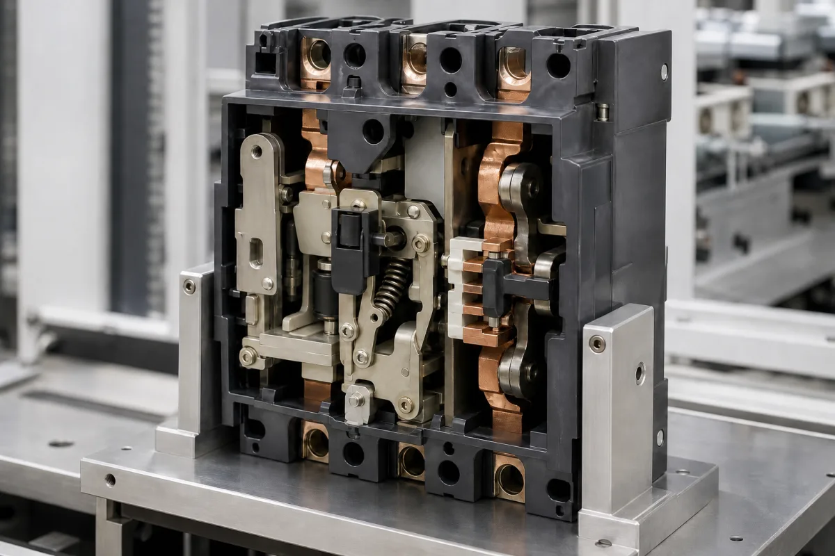
Representative product image. Confirm appearance and specifications with the manufacturer.

Product Specifications

Technical details and manufacturing context for Trip Mechanism

Definition
A trip mechanism is the critical safety component within a circuit breaker responsible for monitoring electrical current. When it detects a fault condition—such as an overload (sustained current above the rated value) or a short circuit (extremely high current surge)—it mechanically actuates to release the latch holding the breaker's contacts closed. This action forces the contacts to separate, thereby opening the circuit and stopping the flow of electricity to prevent damage to the electrical system, wiring, and connected equipment, or to mitigate fire hazards. The mechanism is designed to operate within specified electrical and environmental parameters, including rated voltage up to 690 V AC, rated current up to 630 A, and breaking capacity up to 50 kA, as per IEC 60947 standards. It is constructed from high-strength steel, copper alloy, thermal bimetal, and molded insulating polymer, ensuring mechanical robustness and thermal stability. The trip mechanism is available in various configurations to suit different breaker designs and applications, with mechanical endurance up to 30,000 cycles and electrical endurance up to 5,000 cycles under load. It operates within an ambient temperature range of -40°C to 85°C and relative humidity of 5% to 95% non-condensing, with ingress protection ratings from IP54 to IP65. The trip force required for actuation ranges from 5 to 20 N, and contact resistance is maintained between 0.5 and 2.5 mΩ. The assembly weight varies from 0.5 to 3.5 kg. These values are reference ranges; actual performance must be verified with the manufacturer for the specific model and application. The trip mechanism is a key component in ensuring electrical safety and reliability in industrial and commercial installations.
Working Principle
The mechanism operates based on the principles of electromagnetism and/or thermal expansion. For magnetic (instantaneous) tripping, a solenoid coil generates a magnetic field proportional to the current; a sudden high current creates sufficient magnetic force to attract a plunger, releasing the latch. For thermal (time-delay) tripping, a bimetallic strip heats and bends due to sustained overcurrent, eventually triggering the latch release. Many modern mechanisms combine both thermal and magnetic elements (thermal-magnetic trip) to provide protection against both overloads and short circuits.
Common Materials
High-strength steel, Copper alloy, Thermal bimetal, Molded insulating polymer
Technical Parameters
ParameterTypical rangeNotes & selection driver
Rated Voltage230–690 V ACMaximum operating voltage of the trip mechanism.IEC 60947
Rated Current16–630 AContinuous current capacity.IEC 60947
Breaking Capacity10–50 kAMaximum short-circuit current that can be interrupted.IEC 60947-2
Trip Time0.02–0.1 sTime from fault detection to contact opening.IEC 60947-2
Operating Temperature-40–85 °CAmbient temperature range for reliable operation.IEC 60947-1
Humidity5–95 % RHNon-condensing relative humidity range.IEC 60068-2-78
Ingress ProtectionIP54–IP65Protection against dust and water jets.IEC 60529
Mechanical Endurance10000–30000 cyclesNumber of operations without maintenance.IEC 60947-2
Electrical Endurance1000–5000 cyclesNumber of operations under load.IEC 60947-2
Trip Force5–20 NForce required to actuate the trip mechanism.
Contact Resistance0.5–2.5 Maximum resistance across closed contacts.IEC 60947-4-1
Weight0.5–3.5 kgMass of the trip mechanism assembly.

Ranges are indicative industry figures for RFQ preparation, not a supplier commitment. Confirm every value and standard with the legal manufacturer before ordering.

Components / BOM
  • Bimetallic Strip Part
    Detects sustained overload currents by heating and bending, providing time-delayed thermal tripping.
    Material: Thermal bimetal (two bonded metals with different expansion coefficients)
  • Solenoid / Magnetic Coil Part
    Detects instantaneous short-circuit currents; the magnetic field generated attracts an armature to trigger immediate tripping.
    Material: Copper wire, steel core
  • Trip Latch
    A mechanical latch that holds the breaker contacts closed; released by the actuation of the thermal or magnetic element to open the circuit.
    Material: High-strength steel
  • Calibration Adjustment Part
    Allows for fine-tuning of the trip current setting or sensitivity.
    Material: Steel, polymer

Applied To / Applications

This component is essential for the following industrial systems and equipment:

Industrial Ecosystem & Supply Chain Structure

Complementary Systems
Downstream Applications
Specialized Tooling

Application Fit & Sizing Matrix

Operational Limits
pressure: Atmospheric to 1.5 bar
other spec: Current rating: 0.5A to 6300A, Voltage rating: up to 1000V AC/1500V DC
temperature: -40°C to +85°C
Media Compatibility
✓ Dry air environments ✓ Clean electrical panels ✓ Indoor industrial settings
Unsuitable: High humidity or corrosive atmospheres (e.g., marine, chemical plants)
Sizing Data Required
  • Rated current (Amps)
  • System voltage (Volts)
  • Short-circuit current (kA)

Reliability & Engineering Risk Analysis

Failure Mode & Root Cause
Mechanical binding or jamming
Cause: Accumulation of debris, corrosion, or lack of lubrication in moving parts, preventing proper actuation.
Electrical contact failure
Cause: Wear, oxidation, or contamination of contacts, leading to poor conductivity or false tripping signals.
Maintenance Indicators
  • Unusual grinding, sticking, or delayed response during manual testing
  • Inconsistent or erratic trip indication (e.g., flickering lights, false alarms)
Engineering Tips
  • Implement regular functional testing and lubrication schedules per manufacturer specifications to ensure free movement and contact integrity.
  • Use protective enclosures or environmental controls to minimize exposure to dust, moisture, and corrosive agents.

Indicative industry ranges for design and RFQ preparation. Confirm the exact figures and applicable standard with the manufacturer before specifying.

Compliance & Manufacturing Standards

Applicable Standards
ISO 13849-1: Safety of machinery - Safety-related parts of control systems ANSI/ASME B30.2: Overhead and Gantry Cranes (Top Running Bridge, Single or Multiple Girder, Top Running Trolley Hoist) DIN EN 60947-5-1: Low-voltage switchgear and controlgear - Part 5-1: Control circuit devices and switching elements - Electromechanical control circuit devices

Quoted from the published standard.

Manufacturing Precision
  • Actuation Force: +/-5% of specified value
  • Trip Point Repeatability: +/-0.5% of set value
Quality Inspection
  • Functional Trip Test under Load Conditions
  • Electrical Insulation Resistance Test (e.g., 500V DC, >1MΩ)

Manufacturers of Trip Mechanism

Manufacturer profiles associated with Trip Mechanism.

Sourcing Trip Mechanism from China?
Tell us your specification and target quantity — we will match it against manufacturer records and come back with the factories that fit.
Request manufacturers We manufacture this

Manufacturer listings support early research and capability understanding. They are not certification, ranking, or transaction guarantees.

Technical documentation
Request current drawings, revision history, and a signed specification sheet.
Manufacturing capability
Verify equipment lists, process limits, capacity, and representative production evidence.
Inspection readiness
Confirm test methods, calibrated equipment, sampling plans, and traceable reports.
Supplier transparency
Check the legal entity, factory address, ownership, certifications, and direct contacts.

CNFX does not score or rank suppliers. Buyers must verify all claims and documents with the legal manufacturer before ordering.

Supply Chain Compatible Machinery & Devices

Circuit Breaker Arc Chute

The Circuit Breaker Arc Chute is a critical safety component in electrical circuit breakers, designed to rapidly extinguish electric arcs that form during circuit interruption.

Explore Specs →
Medium Voltage Switchgear Assembly Line

Automated production system for assembling medium voltage electrical switchgear.

Explore Specs →
Motor Terminal Block

A motor terminal block is a standardized electrical component that provides secure, insulated connection points for motor winding leads.

Explore Specs →
PLC Control System

A digital industrial computer control system that monitors inputs, makes decisions based on a custom program, and controls outputs to automate industrial processes.

Explore Specs →

Frequently Asked Questions

What is the function of a trip mechanism in a circuit breaker?

The trip mechanism detects abnormal electrical conditions such as overloads or short circuits and mechanically actuates to open the circuit breaker contacts, interrupting current flow to protect the electrical system and connected equipment.

What are the typical rated voltage and current ranges for a trip mechanism?

According to the directory reference, the rated voltage ranges from 230 to 690 V AC, and the rated current ranges from 16 to 630 A, per IEC 60947. These are reference ranges; actual values must be confirmed for the specific model.

How does a thermal-magnetic trip mechanism work?

It combines a bimetallic strip for thermal overload protection (time-delay) and a solenoid for magnetic short-circuit protection (instantaneous). The thermal element responds to sustained overcurrent, while the magnetic element responds to high current surges.

What standards apply to trip mechanisms?

Relevant standards include IEC 60947 for low-voltage switchgear, IEC 60947-2 for circuit breakers, and IEC 60529 for ingress protection. These standards are references for verification; compliance must be confirmed with the manufacturer.

Data Basis

Editorial classification, named public sources where available, and source-reviewed manufacturer records.

Preliminary Technical Classification
This page supports structured research, RFQ preparation, and supplier evaluation. It does not replace buyer-led supplier qualification, standards review, or technical approval.
Buyer enquiry

Request manufacturing insight for Trip Mechanism

Ask for use case, specification boundaries, supplier type, and RFQ preparation information for this product.

Where it goes
Straight to the CNFX editorial desk, and to the manufacturer if this product is linked to a claimed profile. Nothing is broadcast to a supplier list.
Your details stay here
We do not sell or rent enquiry data, and we do not add you to a mailing list. Used only to answer this request.
No commission, no middleman
CNFX is a directory. We take no cut of any order and never negotiate on a supplier's behalf.
What we don't claim
A listing is not an endorsement. Qualify every supplier and verify every figure yourself before ordering.

Your business information is used only to process this request.

Thank you! Your message has been sent. We'll respond within 1–3 business days.
Sorry, we couldn't send your message. Please try again, or email us at contact@cnfx.com.

Need to Manufacture Trip Mechanism?

Compare manufacturer profiles with relevant product and process capability.

Previous Product
Wire Tensioning System
Last Product
Get QuotesChat