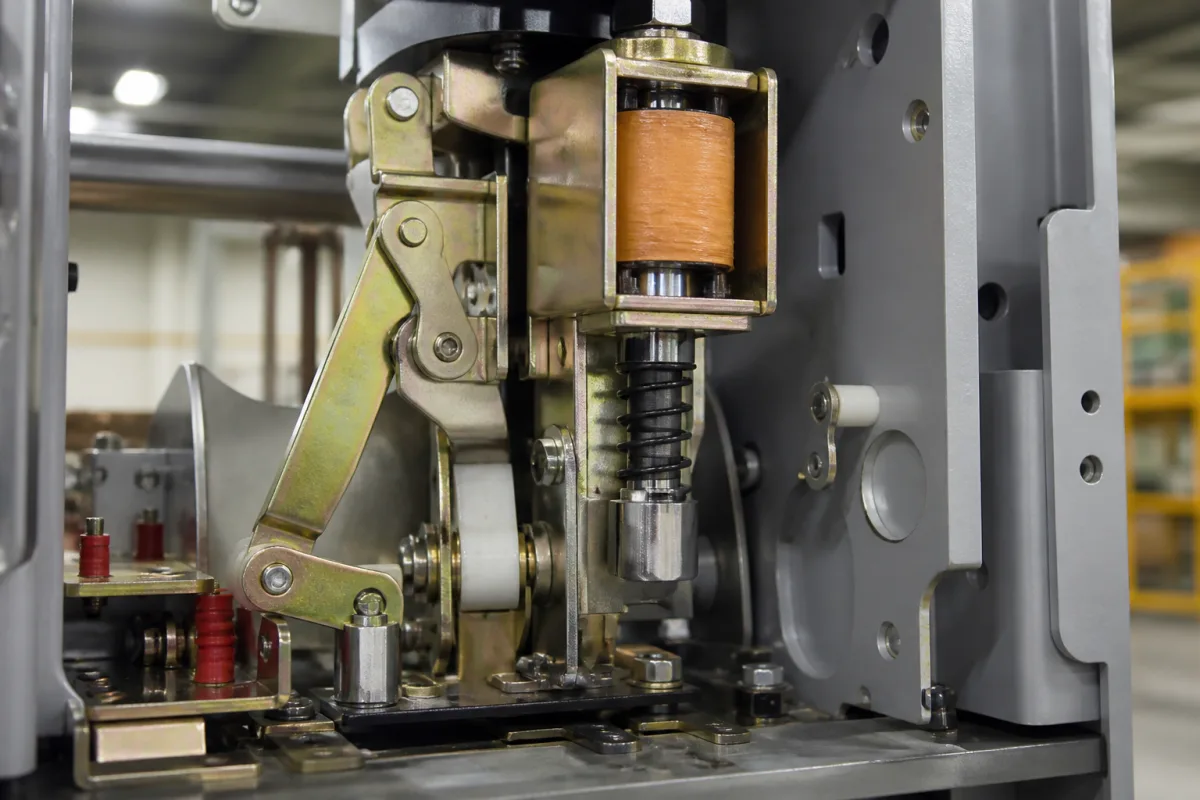
Trip solenoid (shunt opening release) for medium-voltage vacuum circuit-breaker spring mechanisms
The voltage-operated opening coil of a medium-voltage vacuum circuit-breaker · tripping window 70–110 % U on DC, coil power, minimum command time, a second release on its own supply, and plunger mass under shock
In a stored-energy spring mechanism, the trip solenoid is the coil and plunger that, when a relay contact closes, knocks the opening latch free so the charged opening spring separates the vacuum contacts. It does not measure current itself; it obeys a command. Buying one, or a breaker fitted with one, comes down to four things: the control voltage and the window it must trip in, how much power the coil draws and for how long the command must last, whether a second release on a separate supply is needed for safety tripping, and whether the plunger can be shaken into tripping on its own.
Voltage-operated trip coils (shunt opening releases) fitted to the stored-energy spring mechanisms of medium-voltage vacuum circuit-breakers, energised from a battery or AC control supply by protection relays or control switches. Current-operated magnetic trip elements inside molded-case, miniature and motor-protection breakers are covered on the Magnetic trip unit (circuit breaker) page. The complete stored-energy mechanism, its spring timing, motor and endurance are covered on the Spring operating mechanisms for circuit breakers page, which treats the coils only as a load on the control supply; the vacuum bottle itself is on the Medium-voltage vacuum interrupter page. Undervoltage releases, current-transformer operated releases and closing solenoids appear here only where compared.
CNFX editorial research · Sources checked October 12, 2026 · 3 sources
Tripping window: 70–110 % of control voltage on DC, 85–110 % on AC
Siemens' 3AH5 catalogue gives a tripping voltage range for each release fitted to the breaker. A trip coil that still operates at 70 % of its DC rating can trip from a battery that has sagged; the closing solenoid on the same breaker is rated only down to 85 %. [1]
Editorial calculation: on a 110 V DC station battery, 70 % is 77 V and 110 % is 121 V; on a 230 V AC supply, 85 % is 195.5 V and 110 % is 253 V. The undervoltage release in the same table works the other way round: it opens the breaker when its supply falls to 35 % U or below, so it trips on loss of voltage rather than on a command. [1]
ABB's VD4 36/40.5 kV manual offers shunt releases for AC 110, 220 and 240 V and DC 24, 48, 60, 110, 125, 220 and 240 V, with other voltages on request. [2] Siemens describes the shunt release as meant for automatic tripping by protection relays and deliberate electrical tripping from an external DC or AC supply, and, in special cases, from a voltage transformer for manual operation. [1]
State the control voltage and whether it is DC or AC, the lowest voltage at which the coil must still trip (battery end-of-discharge), and the breaker's release designation, because a coil for one voltage cannot be used on another.
02
Coil power, minimum command time and the auxiliary contact that breaks the coil current
A trip coil draws a large current for a few tens of milliseconds. The two makers publish different figures for different designs, which is why the trip relay contact and the control-circuit protection have to be checked against the exact coil fitted.
ABB's manual explains the longer command time: in the VD4 mechanism, auxiliary switch -BB2 interrupts the circuit of shunt release -MO1 once the breaker is open, so the relay contact does not have to break the coil current if the command lasts long enough. [2] Siemens gives opening times below 55 ms with the first shunt release and below 45 ms with the second release, and break times below 70 ms and 60 ms. [1]
Editorial calculation at rated voltage, current = power ÷ voltage: Siemens' 140 W first shunt release on 110 V DC draws about 1.3 A; an ABB release at 250 W on 110 V DC draws about 2.3 A, and at 310 W on 125 V DC about 2.5 A. These are steady-state estimates from the catalogue's approximate power figures; ask for the coil's inrush current and resistance before rating the trip contact or the miniature circuit-breaker on the trip circuit.
ABB's two sets of guideline times for the 36/40.5 kV VD4 differ (opening time up to 45 ms in one, 60 to 90 ms in the other), so confirm which set applies to the ordered breaker type. [2]
A second trip coil for safety tripping, on its own supply
ABB's VD4 manual separates duties: shunt release OFF -MO1 and shunt release ON -MC are exclusively for opening and closing in normal operation, and safety breaking operations must use the second shunt release OFF -MO2, for which the manual refers to a separate control voltage supply. All three are of the solenoid type and suitable for a large number of operating cycles. [2]
The undervoltage release -MU and the indirect overcurrent release -MO3 are, in ABB's words, pure safety and protection releases that must not be used for switching in normal operation. [2] Siemens' 3AH5 allows, besides the closing solenoid, one shunt release plus one further release chosen from a second shunt release (with energy store), an undervoltage release or a current-transformer operated release. [1]
Where there is no battery, Siemens offers current-transformer operated releases with their own stored-energy mechanism: the 3AX11 02 picks up at 90 % of its 0.5 A or 1 A rated normal current, and the 3AX11 04 needs a tripping pulse of at least 0.1 Ws. [1] Editorial note: these are an alternative to a voltage-operated trip solenoid, not a variant of it; choose between them by whether a reliable control supply exists at the switchgear.
Say whether one or two opening releases are needed, which one the protection relay drives, and whether the second must run from a separate supply.
04
Plunger mass and shock: how a trip solenoid can trip without a command
Eaton's patent US 7,064,634 B1 on shock-resistant actuators starts from a weakness of the linear trip solenoid: on a ship or other vehicle, an impact can accelerate the breaker up to, or beyond, 300 g for a very brief time, and the mass of the plunger may then move it as if the coil had been energised. [3]
The patent states that under such a shock a 100 g plunger could exert a force of 3 kilograms. Editorial calculation: 0.1 kg × 300 g gives 30 kgf, so the patent's 3 kg figure corresponds to 30 g rather than 300 g; the point stands either way, but use 30 kgf if checking a latch against a 300 g shock. [3]
Eaton's answer is a rotary solenoid coupled to the trip device by a multi-filament steel wire of about 1.0 to 2.0 g (preferably 1.5 g) with a pull strength of about 50 kg; at 300 g such a link creates only about 0.45 kg, which the solenoid and its spring absorb. [3] Editorial note: for breakers on ships, in seismic zones or near heavy machinery, ask the breaker maker for shock-test evidence covering the trip and close solenoids, not only the vacuum interrupters.
05
What to state when ordering a trip solenoid or a breaker fitted with one
Paste it into your enquiry below or into an email to a maker, then replace every bracket.
Breaker: [make; type; rated voltage; mechanism]
Release: [1st shunt release / 2nd shunt release; designation]
Control supply: [DC or AC; rated voltage; lowest voltage at which it must trip]
Power: [coil W or VA; inrush current; series rectifier or varistor]
Command: [minimum command time; relay contact can or cannot break coil current]
Environment: [shock or vibration level; ambient temperature]
Documents: [wiring diagram; routine test report]
Explore company information and manufacturing capabilities, then discuss the scope of your project with a relevant supplier.
Share this page
Compiled and source-reviewed by the CNFX editorial team.
Each manufacturer above links to the page on that company's own website where the product is listed, with the date we checked it. How we source and review
· Page last updated 13 October 2026
Buyer questions
What voltage range must a breaker trip coil work in?
Siemens rates its 3AH5 shunt releases to trip between 70 and 110 % of rated voltage on DC, and between 85 and 110 % on AC. [1]
How much power does a vacuum breaker trip coil draw?
Siemens lists about 140 W DC for the 3AH5 first shunt release; ABB lists about 250 VA/W, or 310 at 240 V AC and 125 or 240 V DC, for VD4 36/40.5 kV releases. [1][2]
Why fit a second shunt release?
ABB's VD4 manual reserves the first shunt release for normal opening and requires the second for safety breaking operations, with reference to a separate control supply. [2]
Can a shock trip a breaker through its trip solenoid?
Eaton's US 7,064,634 B1 describes plunger mass moving under shocks up to or beyond 300 g, and replaces the plunger link with a 1.5 g steel wire. [3]
Sources and what still needs a direct check
Sources checked 2026-10-12. Tripping ranges, power consumption and operating times come from the Siemens 3AH5 catalogue HG 11.05 (2017) and the ABB VD4 36/40.5 kV instruction manual; the shock behaviour of solenoid plungers from Eaton's US patent 7,064,634 B1.