Editorial Technical Reference

Centrifugal Wheel Assembly

This page explains how Centrifugal Wheel Assembly is classified within Machinery and Equipment Manufacturing. Technical values and manufacturer relationships are research references; confirm the current specification and supplier evidence for each order.

Technical Definition & Core Assembly

A rotating assembly that propels abrasive media at high velocity for surface preparation.

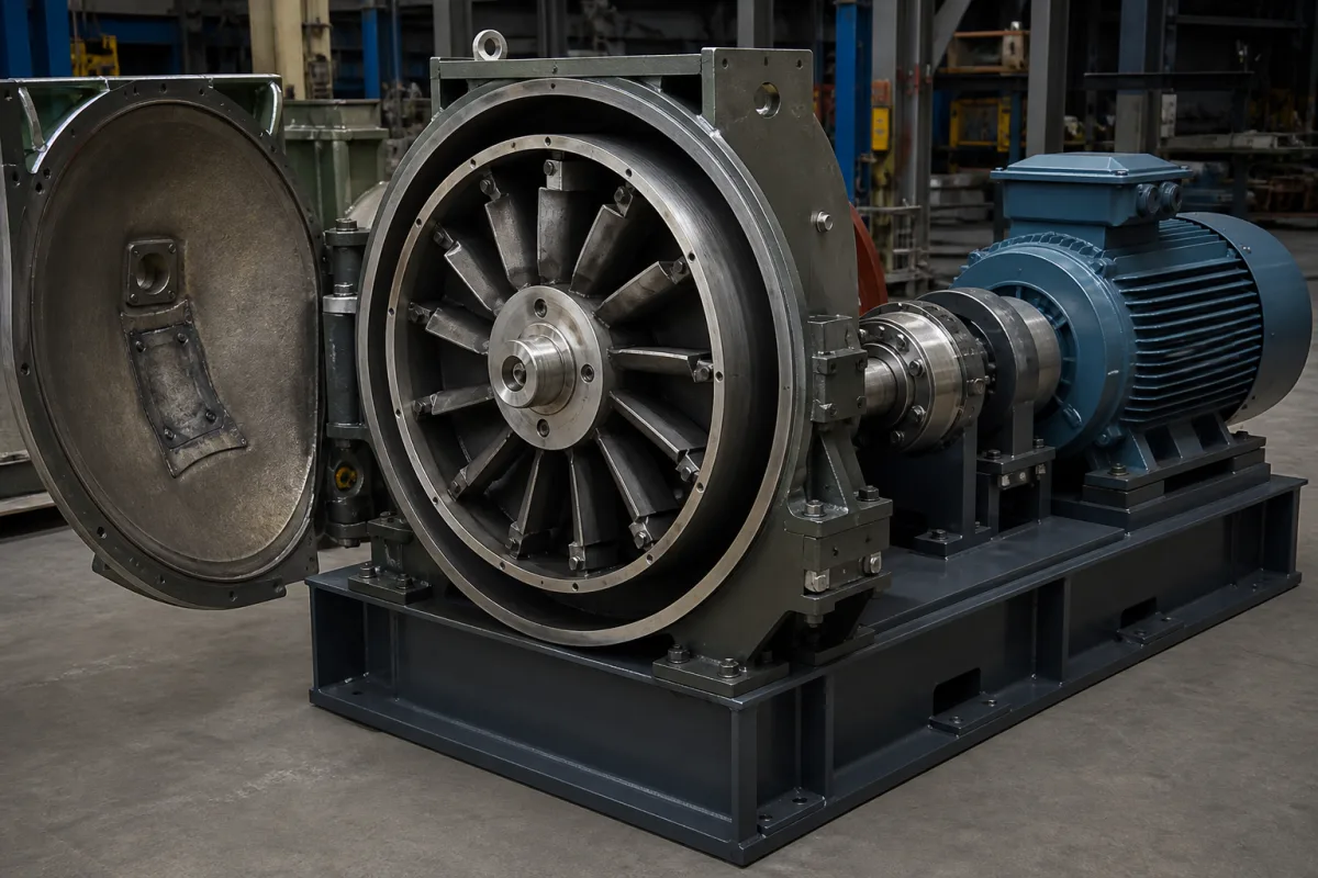
Representative product image. Confirm appearance and specifications with the manufacturer.

Product Specifications

Technical details and manufacturing context for Centrifugal Wheel Assembly

Definition
The centrifugal wheel assembly is a critical component within a Marine Hull Plate Shot Blasting Machine. It is responsible for accelerating abrasive shot or grit via centrifugal force and directing it onto steel hull plates to remove rust, mill scale, and old coatings, preparing the surface for subsequent painting or treatment. This assembly is designed for continuous operation in demanding environments, with materials such as high-chromium cast iron and alloy steel used for wear-resistant parts. Key parameters include a wheel diameter of 250–500 mm, blade width of 40–120 mm, maximum speed of 1800–3600 rpm, abrasive flow rate of 100–500 kg/min, motor power of 5.5–30 kW, operating voltage of 380–690 V AC (IEC 60038), frequency of 50–60 Hz (IEC 60038), maximum operating temperature of 80–120 °C, noise level of 85–105 dB(A) at 1 m (ISO 3744), weight of 50–200 kg, blade hardness of 58–62 HRC (ASTM E18), and balancing grade of G6.3–G2.5 (ISO 21940-11). These values are reference ranges and must be confirmed for the specific model and application. The assembly operates by rotating at high speed; abrasive media fed into the center is captured by blades and ejected outward at high velocity. Proper selection requires consideration of workpiece material, desired surface finish, and production rate. Interfaces include motor mounting, abrasive feed inlet, and discharge opening. Verification questions should address actual operating conditions, such as abrasive type and size, and confirm that the assembly meets required standards. Maintenance signals include increased vibration, noise, or reduced blasting efficiency, indicating blade wear or imbalance. Failure boundaries include exceeding maximum speed or temperature, which can cause bearing failure or structural damage. Always verify model-specific values and standards with the legal manufacturer or supplier.
Working Principle
The assembly rotates at high speed. Abrasive media fed into the center of the rotating wheel is captured by blades or vanes. Centrifugal force accelerates the media outward along the blades and ejects it at high velocity through an opening or nozzle towards the target workpiece. The kinetic energy of the abrasive particles impacts the surface, removing contaminants and preparing it for coating.
Common Materials
High-Chromium Cast Iron, Alloy Steel
Technical Parameters
ParameterTypical rangeNotes & selection driver
Wheel Diameter250–500 mmDetermines coverage area and impact energy
Blade Width40–120 mmAffects abrasive flow rate and pattern
Max Speed1800–3600 rpmHigher speed increases particle velocity
Abrasive Flow Rate100–500 kg/minControls surface coverage and intensity
Motor Power5.5–30 kWSized for wheel inertia and abrasive load
Operating Voltage380–690 V ACThree-phase; other voltages on requestIEC 60038
Frequency50–60 HzCompatible with standard mainsIEC 60038
Max Operating Temperature80–120 °CExceeding may cause bearing failure
Noise Level85–105 dB(A)At 1 m; hearing protection requiredISO 3744
Weight50–200 kgDepends on size and material
Blade Hardness58–62 HRCWear resistance; lower hardness reduces lifeASTM E18
Balancing GradeG6.3–G2.5Higher grade reduces vibrationISO 21940-11

Ranges are indicative industry figures for RFQ preparation, not a supplier commitment. Confirm every value and standard with the legal manufacturer before ordering.

Components / BOM
  • Wheel Disc/Hub Part
    The central rotating disc that forms the base structure of the assembly and mounts to the drive shaft.
    Material: Alloy Steel
  • Blades/Vanes Part
    Radial blades attached to the disc that capture, accelerate, and direct the abrasive media.
    Material: High-Chromium Cast Iron
  • Wear Plate/Control Cage
    A stationary or adjustable component surrounding the wheel that controls the direction and pattern of the ejected abrasive stream.
    Material: High-Chromium Cast Iron
  • Drive Shaft & Bearings
    Transmits rotational power from the motor to the wheel and supports it during high-speed operation.
    Material: Alloy Steel

Industrial Ecosystem & Supply Chain Structure

Complementary Systems
Downstream Applications
Specialized Tooling

Application Fit & Sizing Matrix

Operational Limits
pressure: Atmospheric to 2 bar (29 psi)
flow rate: 50-500 L/min (13-132 gal/min)
temperature: Ambient to 150°C (302°F)
slurry concentration: Up to 30% solids by weight
Media Compatibility
✓ Steel shot/grit ✓ Aluminum oxide ✓ Glass beads
Unsuitable: Highly corrosive acidic environments
Sizing Data Required
  • Required surface coverage rate (m²/hr)
  • Desired surface finish profile (microns)
  • Available power supply (kW)

Reliability & Engineering Risk Analysis

Failure Mode & Root Cause
Imbalance-induced vibration
Cause: Uneven material buildup, wear, or improper assembly leading to mass distribution issues
Bearing fatigue failure
Cause: Inadequate lubrication, contamination ingress, or excessive axial/radial loads
Maintenance Indicators
  • Excessive vibration or audible knocking during operation
  • Unusual temperature rise in bearing housings or shaft
Engineering Tips
  • Implement precision dynamic balancing during assembly and after any component replacement
  • Establish strict lubrication schedules with contamination control and monitor bearing clearances

Indicative industry ranges for design and RFQ preparation. Confirm the exact figures and applicable standard with the manufacturer before specifying.

Compliance & Manufacturing Standards

Applicable Standards
ISO 1940-1:2003 (Balance quality requirements for rotors in a constant state) ANSI/AGMA 2000-A88 (Gear classification and inspection handbook) DIN 45635-1 (Measurement of airborne noise emitted by machines)

Quoted from the published standard.

Manufacturing Precision
  • Bore diameter: +/-0.025mm
  • Wheel axial runout: 0.05mm maximum
Quality Inspection
  • Dynamic balancing test (per ISO 1940-1)
  • Ultrasonic testing for material integrity

Manufacturers of Centrifugal Wheel Assembly

Manufacturer profiles associated with Centrifugal Wheel Assembly.

Sourcing Centrifugal Wheel Assembly from China?
Tell us your specification and target quantity — we will match it against manufacturer records and come back with the factories that fit.
Request manufacturers We manufacture this

Manufacturer listings support early research and capability understanding. They are not certification, ranking, or transaction guarantees.

Technical documentation
Request current drawings, revision history, and a signed specification sheet.
Manufacturing capability
Verify equipment lists, process limits, capacity, and representative production evidence.
Inspection readiness
Confirm test methods, calibrated equipment, sampling plans, and traceable reports.
Supplier transparency
Check the legal entity, factory address, ownership, certifications, and direct contacts.

CNFX does not score or rank suppliers. Buyers must verify all claims and documents with the legal manufacturer before ordering.

Supply Chain Compatible Machinery & Devices

Automated Powder Coating System

Integrated industrial system for applying dry powder coatings to metal substrates.

Explore Specs →
Centrifugal Pump Impeller

The centrifugal pump impeller is a critical rotating component that converts mechanical energy from the motor into kinetic energy in fluid systems.

Explore Specs →
High-Precision CNC Laser Cutting Machine

Computer-controlled industrial machine using focused laser beams to cut sheet metal with micron-level accuracy.

Explore Specs →
Industrial-Grade Hydraulic Cylinder Piston Rod

This industrial-grade piston rod is a precision-ground cylindrical component designed for use in hydraulic cylinders.

Explore Specs →

Frequently Asked Questions

What is the typical wheel diameter range for this assembly?

The wheel diameter is typically in the range of 250–500 mm, but the exact value depends on the specific model and application. Always confirm with the manufacturer or supplier.

What materials are used for the wear parts?

The materials on file include high-chromium cast iron and alloy steel. These are chosen for wear resistance, but the exact grade and treatment should be verified with the supplier.

What standards are relevant for balancing and noise?

Balancing grade is specified per ISO 21940-11 (G6.3–G2.5), and noise level is measured per ISO 3744 (85–105 dB(A) at 1 m). These are reference standards; actual compliance must be confirmed.

How should I verify that the assembly meets my requirements?

You should confirm the actual parameters (e.g., speed, flow rate, motor power) with the legal manufacturer or supplier, and ensure they match your operational needs and any applicable standards.

Data Basis

Editorial classification, named public sources where available, and source-reviewed manufacturer records.

Preliminary Technical Classification
This page supports structured research, RFQ preparation, and supplier evaluation. It does not replace buyer-led supplier qualification, standards review, or technical approval.
Buyer enquiry

Request manufacturing insight for Centrifugal Wheel Assembly

Ask for use case, specification boundaries, supplier type, and RFQ preparation information for this product.

Where it goes
Straight to the CNFX editorial desk, and to the manufacturer if this product is linked to a claimed profile. Nothing is broadcast to a supplier list.
Your details stay here
We do not sell or rent enquiry data, and we do not add you to a mailing list. Used only to answer this request.
No commission, no middleman
CNFX is a directory. We take no cut of any order and never negotiate on a supplier's behalf.
What we don't claim
A listing is not an endorsement. Qualify every supplier and verify every figure yourself before ordering.

Your business information is used only to process this request.

Thank you! Your message has been sent. We'll respond within 1–3 business days.
Sorry, we couldn't send your message. Please try again, or email us at contact@cnfx.com.

Need to Manufacture Centrifugal Wheel Assembly?

Compare manufacturer profiles with relevant product and process capability.

Previous Product
Z-axis Ram/Spindle
Last Product
Get QuotesChat