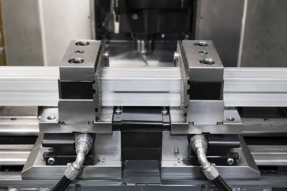
Machine vises and clamping jaws · Workholding vises for CNC machining centres, single or dual station, with fixed and sliding jaws, interchangeable jaw plates, a torque-to-clamping-force ratio, body material and quick-change interfaces for automated loading
A machine vise holds a workpiece between a fixed and a moving jaw on the table of a milling or machining centre; the jaws, which can be interchangeable plates, grip the part and set its position for cutting. Ask three things first: what part sizes and how many parts per setup the vise must hold, how much clamping force the cut needs without distorting the part, and how the vise and jaws will mount, change over and, if needed, be loaded by a robot.
Mechanical, pneumatic and hydraulic machine vises and their clamping jaws for CNC milling and machining centres, including multi-station vises and vises used with zero-point or robot loading. Welding fixtures (see welding fixture jig), test fixtures (see test fixture), lathe chucks and bench vises for hand work are outside this page.
CNFX editorial research · Sources checked October 12, 2026 · 4 sources
Orange Vise lists its 6 in dual-station vise in lengths of 16, 17.5, 20, 22 and 26 in, convertible to single-station use. It states a clamping force ratio of 600 lb per 10 ft-lb of torque and a maximum recommended clamping force of 7,200 lb at 120 ft-lb, with force-to-torque linear across the range and repeatable over time. The 16 in version weighs 110 lb. [1]
Its vise bodies, master sliding jaws, carriers and master centre jaws are Dura-Bar cast iron (black oxided), while hardened bolt-on jaws and narrow centre jaws are steel. [1]
Editorial calculation: 7,200 lb of clamping force is about 32.0 kN, 6 in jaws are about 152 mm wide, and 110 lb is about 50 kg; the stated ratio means 60 lb of clamping force for each ft-lb of torque. [1]
Give the supplier the machine and table interface, part sizes and materials, number of parts per setup (single, dual or multi-station), clamping force limits for thin-walled parts, jaw type (hard, soft, machinable, profile), required repeatability, actuation (manual, pneumatic, hydraulic), zero-point or robot loading needs, and quantity.
02
Choose the jaw interface and automation
Orange Vise fits a quick-change dovetailed jaw interface as standard, compatible with dovetailed quick-change jaws and, optionally, 1/2-13 bolt-on jaws on a 3.875 × 0.9375 in bolt pattern; dovetailed aluminium jaw plates are included, with hard jaws and machinable jaws sold separately. [1]
SCHUNK describes a vise automation system in which operators clamp workpieces into prepared vises outside the machine and load them into a storage rack; a robot with special gripper fingers places each vise on a raised VERO-S 1-way zero-point clamping station on the machine table, which positions and clamps it in one operation with high pull-down force and repeat accuracy, and returns it after machining. SCHUNK says the robot only handles complete vises at fixed positions, so programming reduces to point-to-point moves and no media feed is needed on the machine side. [2]
Kurt Manufacturing's US patent 5,975,513 (filed 1997-10-09, published 1999-11-02) addresses parts lifting as the movable jaw closes. In its angle-lock design the jaw nut acts on the movable jaw through a part-spherical insert, so the clamping load has components both parallel and perpendicular to the way surfaces; an O-ring, elastomer plug or spring-loaded ball holds the unloaded jaw clear of the ways by "a few thousandths" up to about 1/16 in, and when the jaw is tightened that member compresses so the jaw seats on the ways and presses the workpiece down toward the vise bed. The patent cites US 2,880,638 as an early example of the downward-force jaw nut. [3] Editorial calculation: 1/16 in is about 1.6 mm.
03
Clamp plates and large parts with a modular centric system
LANG Technik, a German workholding maker, builds its Makro•Grip Ultra as a modular self-centring clamping system for plates and large components. Base bodies come in three system heights (45, 109 and 189 mm) and are combined with spindles of three lengths for clamping ranges of 40–410, 40–610 and 40–810 mm. Each jaw is held by its own threaded cap, so it can be repositioned without turning the spindle and asymmetrical parts can be clamped. Jaw options are a serrated Makro•Grip Ultra 125 jaw with 3 mm clamping depth, an Avanti base jaw with a hardened plain top jaw, and Avanti top jaws for pre-machined profiles. The system mounts on Quick•Point 96 zero-point units on a 96 mm grid, which LANG states position to better than 0.005 mm. [4]
Centre jaws allow multiple parts to be clamped, with centring plates accepting a 4 mm variation in part length, and a hydraulic screw jack supports thin, wide plates against vibration. [4]
Editorial calculation: moving from the 45 mm to the 189 mm base height on the 410 set raises weight from 12.8 to 43.2 kg, about 3.4 times, and the 810 M set at 51.7 kg is about the weight of the 16 in Orange dual-station vise (110 lb, about 50 kg), which matters for robot or manual handling. [4][1]
The companies in the manufacturer list below show this product on their own websites. Confirm the legal seller, factory and scope for your order.
Ask any supplier for jaw width, opening range per station, clamping force and torque ratio, accuracy (parallelism, squareness, repeatability), body and jaw materials and hardness, jaw interfaces, mounting and zero-point options, actuation, weight and lead time.
05
Trace what each part does
This is a functional reference built from the sources cited; it is not one maker's specification.
Fill the specification fields with values for your order
A vise quotation needs values for your parts and machine. The table explains each field, gives published values where a reviewed source states them, and says what to obtain from the supplier.
Field
What it means and published values
Ask the supplier for
Clamping Range (mm)
Set by vise length (16–26 in models) and jaws. [1]
Explore company information and manufacturing capabilities, then discuss the scope of your project with a relevant supplier.
Share this page
Compiled and source-reviewed by the CNFX editorial team.
Published product pages show what a company offers, not tested performance. Confirm the legal seller, factory and scope for your order. How we source and review
· Page last updated 13 October 2026
Buyer questions
How much clamping force does a CNC vise give?
Orange Vise lists 600 lb per 10 ft-lb of torque, up to 7,200 lb at 120 ft-lb. [1]
What jaw interfaces are available?
Orange Vise uses a quick-change dovetail as standard with optional 1/2-13 bolt-on jaws. [1]
How are vises automated?
SCHUNK has a robot place pre-loaded vises on a VERO-S zero-point station on the machine table. [2]
How does an angle-lock vise stop the part lifting?
Kurt's US patent 5,975,513 describes a jaw nut that pushes the movable jaw both forward and down; a resilient member keeps the unloaded jaw a few thousandths to about 1/16 in off the ways, then compresses so the jaw seats and presses the part toward the bed. [3]
How are very large parts held for 5-sided machining?
One approach is a modular centric system: LANG's Makro•Grip Ultra combines base bodies and spindles for clamping ranges up to 40–810 mm, with serrated jaws of 3 mm clamping depth, on a 96 mm zero-point grid positioning to better than 0.005 mm. [4]
Sources and what still needs a direct check
Sources checked 2026-10-12. Orange Vise makes CNC machine vises; SCHUNK makes clamping and automation systems; LANG Technik makes modular centric clamping systems; Kurt Manufacturing's US patent 5,975,513 describes the hold-down jaw design of its angle-lock vises.