Editorial Technical Reference

Cushion Cylinders

This page explains how Cushion Cylinders is classified within Machinery and Equipment Manufacturing. Technical values and manufacturer relationships are research references; confirm the current specification and supplier evidence for each order.

Technical Definition & Core Assembly

Hydraulic or pneumatic cylinders that provide controlled pressure and cushioning in die cushion systems.
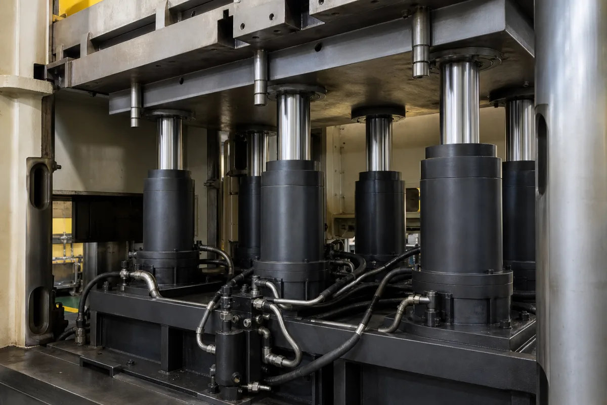
Representative product image. Confirm appearance and specifications with the manufacturer.

Product Specifications

Technical details and manufacturing context for Cushion Cylinders

Definition
Cushion cylinders are specialized hydraulic or pneumatic cylinders that form a critical component of die cushion systems in stamping presses. They provide controlled pressure and cushioning action during the forming process, absorbing impact forces and ensuring smooth operation of the press while protecting dies and workpieces from damage. These cylinders are typically constructed with steel bodies and chrome-plated steel piston rods, with sealing materials such as rubber or polyurethane to ensure reliable operation. Available bore diameters range from 32 to 200 mm (per ISO 6432), with stroke lengths from 25 to 500 mm, and custom strokes up to 2000 mm possible. Operating pressure is typically 1.0 to 1.6 MPa, with a cushioning force adjustable from 500 to 5000 N via a needle valve. The cushioning stroke, which determines deceleration distance, ranges from 10 to 50 mm. Operating temperature is -20 to 80 °C (per ISO 8573-1), and piston speed ranges from 0.1 to 1.5 m/s. Leakage rate is ≤0.05 L/min at nominal pressure (per ISO 10099). The cushioning adjustment range is 0 to 100%, allowing fine-tuning of impact force. Mounting types include flange, foot, and trunnion (per ISO 15552). Weight depends on bore and stroke, ranging from 1.5 to 25 kg. IP ratings of IP54 to IP65 are available for dusty environments. These parameters are reference ranges; always verify model-specific values with the manufacturer or supplier. Cushion cylinders are used in stamping presses to control the blank holder force, prevent wrinkling, and improve part quality. They also reduce shock and noise, extending die life. Proper selection requires consideration of press tonnage, stroke length, required cushion force, and operating speed. Regular maintenance includes checking seals, rod surface, and pressure settings. Failure signs include excessive leakage, erratic cushioning, or unusual noise, indicating seal wear or internal damage. Always consult the manufacturer's documentation for installation, operation, and maintenance guidelines.
Working Principle
Cushion cylinders operate by using hydraulic fluid or compressed air to create controlled resistance during the press stroke. When the press ram descends, the cylinders absorb impact energy through controlled compression of the fluid or gas, providing cushioning at the bottom of the stroke and controlled pressure release during the return stroke. The cushioning force is adjustable via a needle valve, allowing fine-tuning of the deceleration rate. The cushioning stroke determines the distance over which deceleration occurs, and the adjustment range (0-100%) enables precise control of impact force. This principle ensures smooth press operation and protects dies and workpieces from damage.
Common Materials
Steel, Chrome-plated steel, Sealing materials (rubber/polyurethane)
Technical Parameters
ParameterTypical rangeNotes & selection driver
Bore Diameter32–200 mmCommon range; larger sizes available on requestISO 6432
Stroke Length25–500 mmCustom strokes up to 2000 mm possible
Operating Pressure1.0–1.6 MPa
Cushioning Force500–5000 NAdjustable via needle valve
Cushioning Stroke10–50 mmDetermines deceleration distance
Operating Temperature-20–80 °CFor higher temps use special sealsISO 8573-1
Piston Speed0.1–1.5 m/sHigher speeds require external shock absorbers
Leakage Rate≤0.05 L/minAt nominal pressureISO 10099
Cushioning Adjustment Range0–100 %Fine-tune impact force
Mounting TypeISO 15552Available: flange, foot, trunnionISO 15552
Weight1.5–25 kgDepends on bore and stroke
IP RatingIP54–IP65Higher protection for dusty environmentsIEC 60529

Ranges are indicative industry figures for RFQ preparation, not a supplier commitment. Confirm every value and standard with the legal manufacturer before ordering.

Components / BOM
  • Cylinder Barrel
    Main housing that contains the piston and hydraulic fluid
    Material: Steel
  • Piston Part
    Moves within the barrel to create pressure differential
    Material: Steel with sealing rings
  • Piston Rod Part
    Transmits force from the piston to the external load
    Material: Chrome-plated steel
  • Seals Part
    Prevent fluid leakage between moving parts
    Material: Rubber or polyurethane
  • End Caps Part
    Seal the ends of the cylinder barrel
    Material: Steel
  • Needle Valve
    Meters the fluid escaping the cushion, which is what sets how fast the ram decelerates.

Applied To / Applications

This component is essential for the following industrial systems and equipment:

Industrial Ecosystem & Supply Chain Structure

Complementary Systems
Downstream Applications
Specialized Tooling

Application Fit & Sizing Matrix

Operational Limits
pressure: Up to 210 bar hydraulic, 10 bar pneumatic (typical)
other spec: Flow rate: 0-100 L/min hydraulic, 0-5000 NL/min pneumatic; Stroke length: 50-500 mm; Cushioning adjustment: 0-100%
temperature: -20°C to +80°C (standard), -40°C to +120°C (special seals)
Media Compatibility
✓ Hydraulic oil (ISO VG 32-68) ✓ Compressed air (filtered, lubricated) ✓ Water-glycol hydraulic fluids
Unsuitable: Saltwater/marine environments without special corrosion protection
Sizing Data Required
  • Required cushioning force (kN)
  • Available mounting space/envelope dimensions
  • Required cushioning stroke length (mm)

Reliability & Engineering Risk Analysis

Failure Mode & Root Cause
Seal degradation
Cause: Chemical incompatibility with hydraulic fluid, excessive heat, or contamination leading to hardening, cracking, or extrusion of seals, resulting in internal or external leakage.
Rod scoring or pitting
Cause: Ingress of abrasive contaminants (e.g., dirt, metal particles) due to inadequate rod wiper seals or poor environmental protection, causing wear on the rod surface and potential seal damage.
Maintenance Indicators
  • Visible external hydraulic fluid leakage around the rod seal or cylinder body, indicating seal failure.
  • Audible knocking or chattering during the cushioning phase at the end of stroke, suggesting improper cushion adjustment, air entrapment, or internal damage.
Engineering Tips
  • Implement strict contamination control: use high-quality filters in the hydraulic system, ensure proper rod wiper seals are installed and maintained, and keep the rod clean and protected from environmental debris.
  • Regularly inspect and adjust cushioning mechanisms: verify cushion needle valves are correctly set to prevent impact damage, and monitor for signs of wear or misalignment that could lead to uneven loading or side thrust on the rod.

Indicative industry ranges for design and RFQ preparation. Confirm the exact figures and applicable standard with the manufacturer before specifying.

Compliance & Manufacturing Standards

Applicable Standards
ISO 6020-1: Hydraulic fluid power - Mounting dimensions for single rod cylinders, 16 MPa (160 bar) series ANSI/B93.5: Hydraulic Fluid Power - Cylinders - Dimensions and Mountings DIN 24554: Hydraulic cylinders; single-acting, with tie rod; series 16 MPa (160 bar)

Quoted from the published standard.

Manufacturing Precision
  • Bore diameter: +/-0.02 mm
  • Rod straightness: 0.1 mm per 1000 mm length
Quality Inspection
  • Pressure test: 1.5 times maximum operating pressure for 5 minutes
  • Dimensional verification: Critical dimensions checked with calibrated gauges

Manufacturers of Cushion Cylinders

Manufacturer profiles associated with Cushion Cylinders.

Sourcing Cushion Cylinders from China?
Tell us your specification and target quantity — we will match it against manufacturer records and come back with the factories that fit.
Request manufacturers We manufacture this

Manufacturer listings support early research and capability understanding. They are not certification, ranking, or transaction guarantees.

Technical documentation
Request current drawings, revision history, and a signed specification sheet.
Manufacturing capability
Verify equipment lists, process limits, capacity, and representative production evidence.
Inspection readiness
Confirm test methods, calibrated equipment, sampling plans, and traceable reports.
Supplier transparency
Check the legal entity, factory address, ownership, certifications, and direct contacts.

CNFX does not score or rank suppliers. Buyers must verify all claims and documents with the legal manufacturer before ordering.

Supply Chain Compatible Machinery & Devices

Heavy-Duty CNC Plasma Cutting Machine

The Heavy-Duty CNC Plasma Cutting Machine is a standalone industrial device designed for cutting conductive metals such as steel, stainless steel, aluminum, and copper alloys.

Explore Specs →
Automated Powder Coating System

Integrated industrial system for applying dry powder coatings to metal substrates.

Explore Specs →
Centrifugal Pump Impeller

The centrifugal pump impeller is a critical rotating component that converts mechanical energy from the motor into kinetic energy in fluid systems.

Explore Specs →
High-Precision CNC Laser Cutting Machine

Computer-controlled industrial machine using focused laser beams to cut sheet metal with micron-level accuracy.

Explore Specs →

Frequently Asked Questions

What is the typical bore diameter range for cushion cylinders?

The common bore diameter range is 32 to 200 mm, per ISO 6432. Larger sizes may be available on request, but you should confirm with the manufacturer for your specific application.

How is the cushioning force adjusted?

The cushioning force is adjustable via a needle valve, with a range of 500 to 5000 N. This allows fine-tuning of the impact force to suit the forming process.

What operating temperature range is typical?

The typical operating temperature range is -20 to 80 °C, per ISO 8573-1. For higher temperatures, special seals may be required; consult the manufacturer.

What maintenance is required for cushion cylinders?

Regular maintenance includes checking seals, rod surface, and pressure settings. Look for signs of leakage, erratic cushioning, or unusual noise, which may indicate seal wear or internal damage. Always follow the manufacturer's guidelines.

Data Basis

Editorial classification, named public sources where available, and source-reviewed manufacturer records.

Preliminary Technical Classification
This page supports structured research, RFQ preparation, and supplier evaluation. It does not replace buyer-led supplier qualification, standards review, or technical approval.
Buyer enquiry

Request manufacturing insight for Cushion Cylinders

Ask for use case, specification boundaries, supplier type, and RFQ preparation information for this product.

Where it goes
Straight to the CNFX editorial desk, and to the manufacturer if this product is linked to a claimed profile. Nothing is broadcast to a supplier list.
Your details stay here
We do not sell or rent enquiry data, and we do not add you to a mailing list. Used only to answer this request.
No commission, no middleman
CNFX is a directory. We take no cut of any order and never negotiate on a supplier's behalf.
What we don't claim
A listing is not an endorsement. Qualify every supplier and verify every figure yourself before ordering.

Your business information is used only to process this request.

Thank you! Your message has been sent. We'll respond within 1–3 business days.
Sorry, we couldn't send your message. Please try again, or email us at contact@cnfx.com.

Need to Manufacture Cushion Cylinders?

Compare manufacturer profiles with relevant product and process capability.

Previous Product
Z-axis Ram/Spindle
Last Product
Get QuotesChat