Editorial Technical Reference

Cutter Head

This page explains how Cutter Head is classified within Machinery and Equipment Manufacturing. Technical values and manufacturer relationships are research references; confirm the current specification and supplier evidence for each order.

Technical Definition & Core Assembly

The rotating cutting assembly at the front of a foundation drilling machine that excavates soil and rock.
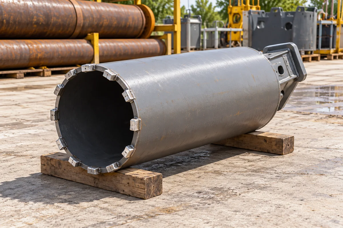
Cutter Head in a manufacturing environment
Representative product image. Confirm appearance and specifications with the manufacturer.

Product Specifications

Technical details and manufacturing context for Cutter Head

Definition
A cutter head is the primary excavation component of a foundation drilling machine, mounted at the end of the drill string or Kelly bar. It rotates to cut through various geological formations including soil, clay, sand, and rock, creating the borehole for foundation piles, diaphragm walls, or other deep foundation elements. The design varies based on ground conditions and drilling method (e.g., CFA, rotary, full-displacement). The cutter head is rotated by the drilling machine's rotary drive (top-head or Kelly system) while downward force (crowd) is applied. Cutting teeth or picks on the head break up the ground material. In wet drilling, drilling fluid (bentonite slurry or polymer) is pumped through the hollow stem to flush cuttings to the surface. The head may include mixing paddles or wings to homogenize the soil with fluid for continuous flight auger (CFA) piles. Typical cutter head diameters range from 800 to 3000 mm, with 4 to 12 cutters depending on rock hardness. Torque ratings vary from 50 to 300 kN·m, and rotation speeds from 5 to 40 rpm. Operating pressure is typically 1.0 to 1.6 MPa, with a maximum operating temperature of 80°C and minimum of -20°C. Materials include high-strength alloy steel (e.g., 42CrMo per GB/T 3077), tungsten carbide for teeth, and abrasion-resistant steel plate. Hardness is typically HRC 45–55. Weight ranges from 1 to 10 tons. IP ratings are IP54–IP65. These values are reference ranges; verify model-specific specifications with the manufacturer.
Working Principle
The cutter head is rotated by the drilling machine's rotary drive (top-head or Kelly system) while downward force (crowd) is applied. Cutting teeth or picks on the head break up the ground material. In wet drilling, drilling fluid (bentonite slurry or polymer) is pumped through the hollow stem to flush cuttings to the surface. The head may include mixing paddles or wings to homogenize the soil with fluid for continuous flight auger (CFA) piles.
Common Materials
High-strength alloy steel, Tungsten carbide (for teeth/picks), Abrasion-resistant steel plate
Technical Parameters
ParameterTypical rangeNotes & selection driver
Cutter Head Diameter800–3000 mmDetermines borehole diameter
Number of Cutters4–12More cutters for harder rock
Cutter Head Torque50–300 kN·mHigher torque for tough formations
Rotation Speed5–40 rpmAdjustable for soil type
Max Operating Temperature80 °CExceeding may damage seals
Min Operating Temperature-20 °CBelow may cause brittleness
Material Grade42CrMoHigh strength alloy steelGB/T 3077
HardnessHRC 45–55Wear resistance
Weight1–10 tDepends on diameter and material
IP RatingIP54–IP65Protection against dust and waterIEC 60529

Ranges are indicative industry figures for RFQ preparation, not a supplier commitment. Confirm every value and standard with the legal manufacturer before ordering.

Components / BOM
  • Main Body/Plate Part
    Structural core that mounts cutting teeth and connects to drill string.
    Material: High-strength steel plate (e.g., Hardox)
  • Cutting Teeth/Picks Part
    Replaceable carbide-tipped tools that penetrate and break ground material.
    Material: Tungsten carbide inserts on steel holders
  • Mixing Paddles/Wings Part
    Blades that mix excavated soil with drilling fluid for CFA applications.
    Material: Abrasion-resistant steel
  • Central Nozzle/Port Part
    Opening for drilling fluid discharge at the cutting face.
    Material: Hardened steel

Application & selection

Application Fit & Sizing Matrix

Operational Limits
pressure: Up to 10 bar hydraulic pressure
flow rate: 50-300 L/min for flushing/cooling
temperature: -20°C to +80°C
slurry concentration: Up to 40% solids by weight
Media Compatibility
✓ Clay soils ✓ Sand and gravel formations ✓ Soft to medium-hard rock (e.g., limestone, sandstone)
Unsuitable: Extremely hard abrasive rock (e.g., granite, quartzite) without specialized tooling
Sizing Data Required
  • Drill diameter (mm/inches)
  • Maximum torque requirement (kNm/ft-lbs)
  • Ground conditions/rock strength (MPa/psi)

Risk, maintenance & compliance

Reliability & Engineering Risk Analysis

Failure Mode & Root Cause
Bearing fatigue and seizure
Cause: Inadequate lubrication, contamination ingress, or excessive loading leading to overheating and premature wear
Cutting edge degradation and chipping
Cause: Material fatigue from cyclic stress, improper material selection, or impact with foreign objects during operation
Maintenance Indicators
  • Unusual grinding or screeching noises during operation indicating bearing or gear issues
  • Excessive vibration or wobble in the cutter head assembly suggesting imbalance or component wear
Engineering Tips
  • Implement condition-based monitoring with vibration analysis and thermography to detect early-stage bearing and alignment issues
  • Establish a preventive maintenance schedule for lubrication system checks and cutting edge inspections with proper torque specifications during reassembly

Indicative industry ranges for design and RFQ preparation. Confirm the exact figures and applicable standard with the manufacturer before specifying.

Compliance & Manufacturing Standards

Applicable Standards
ISO 15641:2001 (Milling cutters for high-speed machining) ANSI B94.19-1997 (Milling Cutters and End Mills) DIN 844 (Milling cutters with parallel shank)

Quoted from the published standard.

Manufacturing Precision
  • Bore diameter: +/-0.01mm
  • Cutting edge runout: 0.02mm maximum
Quality Inspection
  • Dimensional verification with CMM (Coordinate Measuring Machine)
  • Hardness testing (Rockwell C scale) for cutting edges
Technical documentation
Request current drawings, revision history, and a signed specification sheet.
Manufacturing capability
Verify equipment lists, process limits, capacity, and representative production evidence.
Inspection readiness
Confirm test methods, calibrated equipment, sampling plans, and traceable reports.
Supplier transparency
Check the legal entity, factory address, ownership, certifications, and direct contacts.

Compare the published product scope and source details, then include your specifications and quantity in an enquiry.

Manufacturers of Cutter Head

1 company lists this product among what they make. Company figures are quoted from each company's own website; every card states where the relationship came from.

Zhuzhou Lihua Cemented Carbide Co.,Ltd.
Huzhou, Zhejiang, CN
Also makes: Spray Nozzle, Tool Holder
Listed on the company's own website · profile compiled by CNFX from public sources
Listed there as: “1-steel-turning-cutter-head-”
View source page ↗ lihuacarbide.com · recorded 2026-08-28

Explore company information and manufacturing capabilities, then discuss the scope of your project with a relevant supplier.

Buyer enquiry

Request manufacturing insight for Cutter Head

Ask for use case, specification boundaries, supplier type, and RFQ preparation information for this product.

Where it goes
Straight to the CNFX editorial desk, and to the manufacturer if this product is linked to a claimed profile. Nothing is broadcast to a supplier list.
Your details stay here
We do not sell or rent enquiry data, and we do not add you to a mailing list. Used only to answer this request.
No commission, no middleman
CNFX is a directory. We take no cut of any order and never negotiate on a supplier's behalf.
What to include
Share your product specifications, quantity, destination and target delivery date.

Your business information is used only to process this request.

Thank you! Your message has been sent. We'll respond within 1–3 business days.
Sorry, we couldn't send your message. Please try again, or email us at [email protected].

Frequently Asked Questions

What is the function of a cutter head?

The cutter head is the rotating cutting assembly at the front of a foundation drilling machine. It excavates soil and rock to create boreholes for foundation piles, diaphragm walls, or other deep foundation elements.

What materials are used in cutter heads?

Cutter heads are typically made from high-strength alloy steel (e.g., 42CrMo), with tungsten carbide teeth or picks for cutting, and abrasion-resistant steel plate for wear protection.

What are typical diameter ranges?

Cutter head diameters typically range from 800 to 3000 mm, depending on the required borehole diameter. The number of cutters varies from 4 to 12, with more cutters for harder rock.

How does the cutter head work?

The cutter head is rotated by the drilling machine's rotary drive while downward force is applied. Cutting teeth break up the ground, and drilling fluid flushes cuttings to the surface. Mixing paddles may homogenize soil with fluid for CFA piles.

Related equipment

Applied To / Applications

This component is essential for the following industrial systems and equipment:

Industry Taxonomies & Aliases

Commonly used trade names and technical identifiers for Cutter Head.

Data Basis

Editorial classification, named public sources where available, and source-reviewed manufacturer records.

Preliminary Technical Classification
This page supports structured research, RFQ preparation, and supplier evaluation. It does not replace buyer-led supplier qualification, standards review, or technical approval.

Need to Manufacture Cutter Head?

Compare manufacturer profiles with relevant product and process capability.

Previous Product
Crusher/Pulverizer
Next Product
Cutting Head
Get QuotesChat