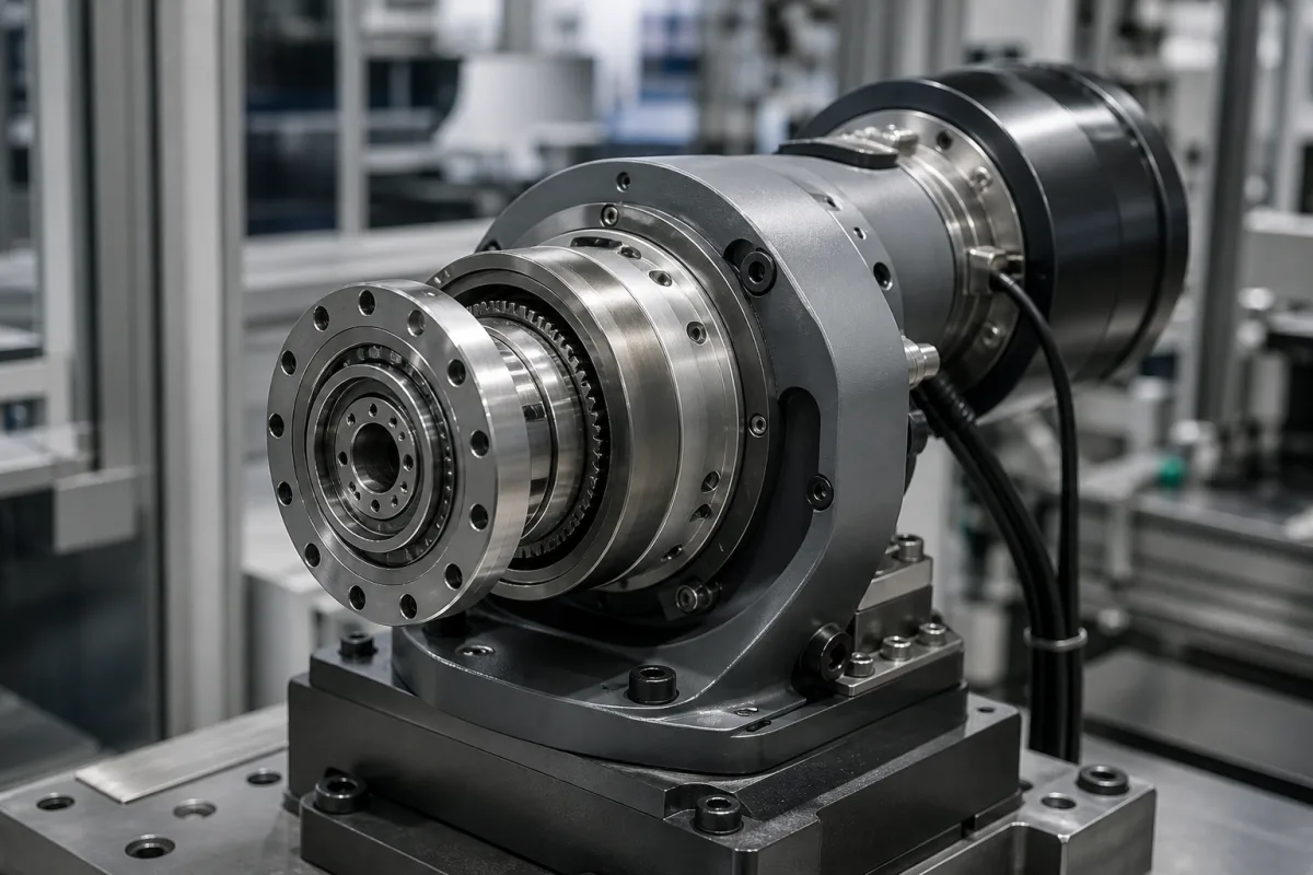
Strain wave (harmonic) gearing · wave generator, flexspline and circular spline with two extra teeth, high single-stage ratios with zero backlash, torsional stiffness and cyclic gear error, temperature and alignment effects, and what to specify for robots and precision pointing
Harmonic drive gears, or strain wave gearing, reduce speed by flexing a thin toothed cup: an elliptical wave generator inside the flexspline pushes its teeth into a rigid internal-toothed circular spline at two opposite points, and because the circular spline has two more teeth, each input turn moves the flexspline back by two teeth. Ask three things first: what ratio and torque the axis needs, how stiff and accurate the output must be, and how the gear will be mounted, aligned and lubricated.
Strain wave gear component sets, units and gearheads for robots, positioners, aerospace mechanisms and precision instruments. Planetary gear reducers (a separate product page), cycloidal reducers, worm gears and harmonic filters for power systems are outside this page except where compared.
CNFX editorial research · Sources checked October 12, 2026 · 4 sources
Harmonic Drive LLC describes strain wave gearing, invented by C. Walton Musser and patented in 1955, as three parts. The wave generator is a thin-raced ball bearing on an elliptical hub, the input connected to the motor; the flexspline is a thin alloy-steel cup with external teeth, radially compliant but torsionally stiff, which takes the elliptical shape and is used as the output; and the circular spline is a rigid internally toothed ring with two more teeth than the flexspline, fixed to the housing. Teeth engage at two regions on the major axis; for every 180° of wave generator rotation the flexspline advances one tooth the opposite way, two teeth per full turn, and continuous engagement gives zero backlash. It states that size and weight do not vary with ratio, and that its S tooth profile allows up to 30% of the teeth to engage simultaneously. [1]
Editorial calculation: since the flexspline moves two teeth per input revolution, a flexspline with 200 teeth needs 200 / 2 = 100 input revolutions for one output revolution, a 100:1 reduction in a single stage. The tooth count is an assumed example; confirm the catalogue ratio and which element is fixed in your arrangement.
Give the supplier the required ratio, rated and peak output torque, input speed, torsional stiffness target, positional accuracy and repeatability, allowable gear error and its frequency content, component set or housed unit, mounting and bearing arrangement, alignment tolerances, lubrication (grease or oil) and temperature range, life and duty cycle, and vacuum or space requirements if any.
02
Check gear error, stiffness and alignment
A paper published through NASA by TRW engineers notes that harmonic drives are known for high reduction ratios, low weight, small volume, zero backlash and high efficiency, but have soft torsional stiffness and gear error. Gear error is the difference between theoretical and measured angular position; all drives tested showed a significant first harmonic, occurring twice per input rotation, while higher harmonics varied between units. Life tests showed only small changes (about 0.008° peak-to-peak at most) over millions of degrees of output travel; over about 56 °C the error magnitude varied about 20% in a repeatable way; concentricity and parallelism of the parts influenced error amplitude; gear error improved with drive size; and electronic compensation was substantially effective for first-harmonic-dominant units. It lists sources including tooth placement errors, out-of-roundness of flexspline, circular spline and bearing race, wall-thickness variation and misalignment between flexspline and circular spline. [2]
Editorial calculation: 0.008° equals 0.008 × 3,600 ≈ 29 arc-seconds. With a 100:1 ratio and an input at 3,000 rpm, the first-harmonic error at twice per input turn repeats 2 × 3,000 / 60 = 100 times a second; check that this frequency stays clear of the structure's resonances. Ratio and speed are assumed examples.
Wear changes these properties. Raviola, De Martin and Sorli (Politecnico di Torino, Actuators 11(11):305, 2022) introduced wear into strain wave gears from two suppliers and measured torsional stiffness. The effect depended on both the maker and where the wear occurred: damage at the wave generator–flexspline interface cut stiffness to as little as one-quarter of nominal, while worn, out-of-shape teeth cut it to as little as 4% of nominal and introduced backlash. [3]
Editorial note: zero backlash and catalogue stiffness describe a new gear; for long-life or safety-relevant axes, ask the supplier for stiffness and lost-motion data after life testing, and plan a check of torsional stiffness as part of maintenance. [3][2]
03
Read the ratio and tooth-contact rules in the original patent
The founding patent, US 2,906,143 "Strain wave gearing" by C. Walton Musser, was filed on 21 March 1955 and published on 29 September 1959, assigned to United Shoe Machinery Corp. Its worked example uses a ring gear (the circular spline) with 200 teeth and a strain gear (the flexspline) with 198 teeth, driven by a two-lobe elliptical strain inducer (the wave generator). The patent states that one revolution of the strain wave moves the teeth by the difference in tooth count, and that the tooth differential equals the number of lobes, two in this case. [4]
Run backwards, with the strain gear held and the ring gear driving, the patent says the strain inducer makes 100 revolutions for every revolution of the ring gear. It lists as objects of the invention gear ratios between 10 to 1 and 1 million to 1, keeping more than 50% of the teeth of both gears in contact, surface rather than point or line contact, and insensitivity to misalignment between input and output. Gears made to the basic dimensions of its Figure 17 have 55 percent of their teeth in contact, of which 27.5 percent are actively load-bearing under torque, and the patent states the gear can be made completely without backlash. [4]
Editorial calculation: with the ring gear held and the 198-tooth strain gear as output, ratio = 198 ÷ (200 − 198) = 99:1; with the strain gear held and the 200-tooth ring gear as output, ratio = 200 ÷ 2 = 100:1, matching the patent's 100 revolutions. The element you fix changes the ratio by one and reverses or keeps the output direction, so state the fixed element in the order. [4][1]
The patent's 55% figure describes its own tooth geometry; Harmonic Drive LLC's current page claims up to 30% simultaneous engagement for its S tooth profile. The two figures are not measured on the same basis, so ask the supplier how its engagement figure is defined. [4][1]
China Harmonic Drive lists units and component sets in GB, P and U series, and Hanzhen its XB1, XB2 and XB3 series and harmonic gearboxes; the product forms below are described in the sources cited.
Products range from component sets (wave generator, flexspline and circular spline) built into the user's housing to complete gearheads with output flanges; makers also offer S-type tooth profiles and units for space mechanisms. [1][2]
05
Wave generator, flexspline, circular spline, output bearing and lubrication
The flexspline and circular spline rows carry the error sources listed in the NASA-published tests: tooth placement, out-of-roundness, wall-thickness variation and misalignment between the two. [2]
Part
Role
Fix in the order
Wave generator
Elliptical hub with thin-raced bearing; input. [1]
Ratio, backlash, gear error, temperature effect, stiffness and tooth engagement for a strain wave gear
The gear error, temperature and stiffness figures are test results on particular drives, from the NASA-published tests and the 2022 wear study, not catalogue values; ask for the supplier's own curves. [2][3]
Field
What it means and published values
Ask the supplier for
Ratio
Two-tooth difference sets ratio; single stage. [1]
Catalogue ratio.
Backlash
Zero backlash claimed when new; tooth wear can introduce backlash. [1][2][3]
Lost motion data.
Gear error
First harmonic at 2× input; ~0.008° change over life (tests). [2]
2 companies list this product among what they make. Company figures are quoted from each
company's own website; every card states where the relationship came from.
China Harmonic Drive (CHD®)
Manufacturing site to be confirmed for the order
Lists harmonic drive units and component sets, with GB, P and U series and actuators.
Product scope checked 2026-10-12
Harmonic drive listed · profile compiled by CNFX from public sources
Explore company information and manufacturing capabilities, then discuss the scope of your project with a relevant supplier.
Share this page
Compiled and source-reviewed by the CNFX editorial team.
Each manufacturer above links to the page on that company's own website where the product is listed, with the date we checked it. How we source and review
· Page last updated 13 October 2026
Buyer questions
How does a harmonic drive get its ratio?
Harmonic Drive LLC explains the circular spline has two more teeth than the flexspline, so each wave generator turn moves the flexspline two teeth. [1]
Do harmonic drives have backlash?
They are described as zero-backlash because teeth stay fully engaged along the ellipse's major axis. [1]
What limits harmonic drive precision?
NASA-published tests highlight soft torsional stiffness and a cyclic gear error dominated by a first harmonic at twice per input rotation. [2]
Does a worn harmonic drive lose stiffness?
A 2022 Actuators study found wave generator–flexspline damage cut stiffness to about one-quarter of nominal and worn teeth to as little as 4%, with backlash appearing. [3]
Who invented strain wave gearing and what ratio did the patent show?
C. Walton Musser's US patent 2,906,143, filed in 1955 and assigned to United Shoe Machinery Corp, uses a 200-tooth ring gear and a 198-tooth strain gear; with the strain gear held, the strain inducer turns 100 times per ring-gear revolution. [4]
Sources and what still needs a direct check
Sources checked 2026-10-12. Harmonic Drive LLC describes its own strain wave gearing; Musser's 1955 US patent, assigned to United Shoe Machinery Corp, sets out the original tooth-count and ratio rules; the NASA Technical Reports Server paper by TRW engineers reports tests on harmonic drives for spacecraft mechanisms; a 2022 Actuators paper measures stiffness after wear.