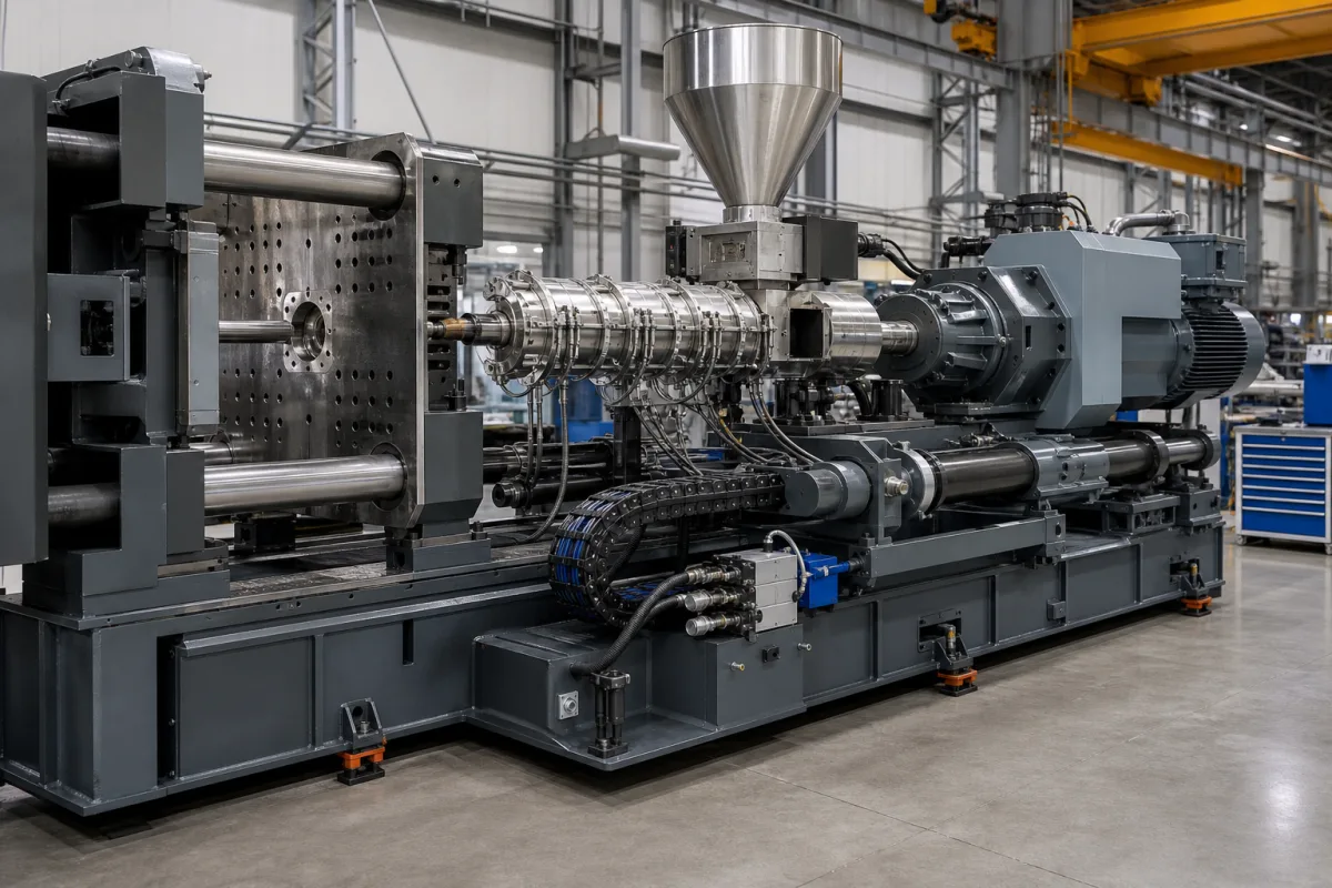
Injection drive and control system for plastics injection moulding machines
Plastics injection moulding · The drive and control that push the screw forward: velocity-to-pressure switchover, hydraulic, servo-hydraulic or all-electric actuation, response time and energy per kilogram
In a plastics injection moulding machine the injection system's drive pushes the screw forward to fill the mould at a set speed, then switches to holding the melt at a set pressure while the part cools. Whether that motion comes from a hydraulic cylinder fed by a fixed or variable pump, a servo-driven pump, or a servo motor and ball screw decides how precisely the speed, the switchover point and the holding pressure are held, and how much power is drawn while nothing moves.
Injection drives and their control on plastics injection moulding machines: hydraulic injection cylinders with fixed-displacement, variable-displacement or servo-driven pumps, electric injection with servo motors and ball screws, and the velocity, switchover and holding-pressure control. Shot ends that inject molten metal are covered on the High-pressure die casting machine page, and hot-work steel cavity inserts for die-casting dies on their own page; plasticising barrels and screws are covered on the Injection unit barrel and screw page, and whole-machine selection on the Injection molding machine page.
CNFX editorial research · Sources checked October 12, 2026 · 3 sources
Switching from injection speed to holding pressure: screw position or cavity pressure
Hopmann and co-authors at IKV Aachen write that the ideal switchover is when the melt front reaches the end of the flow path. Switching too early drops cavity pressure and can leave switchover or sink marks; switching too late produces pressure peaks that can cause high residual stress and flash. Of the switchover methods, screw-position and cavity-pressure triggering have become established, both with high reproducibility; temperature sensors in the mould respond with a delay of a few milliseconds, which makes that method unreproducible. [1]
IKV moulded plates of polypropylene of about 27 g on an Arburg Allrounder 370 A and varied seven settings to simulate disturbances, measuring ten parts per setting. Part weight and length varied by comparable amounts with either method, but the standard deviation of width was 0.067 mm lower with cavity-pressure switchover. Lengthening cooling time by 1 s made parts 0.129 mm longer with screw-position switchover and 0.209 mm longer with cavity-pressure switchover, and raising mould temperature lengthened parts with one method and shortened them with the other. [1]
The authors conclude that a standardised setup for different switchover methods is not feasible for consistent part quality, and describe a phaseless control in which a model-based controller makes cavity pressure follow a reference trajectory, here converging to 250 bar, without a switchover point. [1]
Setting varied in the IKV trials
Base value
Variation
Injection velocity
21 mm/s
± 10 mm/s
Packing pressure
250 bar
± 25 bar
Cooling time
12 s
± 5 s
Dosing volume
45 cm³
± 2 cm³
Back pressure
60 bar
± 5 bar
Nozzle temperature
240 °C
± 13 °C
Mould temperature
40 °C
± 6 °C
State which switchover signal the machine must accept (screw position, hydraulic or melt pressure, cavity pressure input), how many injection-speed and holding-pressure stages are needed, and the shot volume and injection speed range of your parts.
02
Fixed pump, variable pump, servo pump or ball screw
Efficiency Vermont's ACEEE paper explains that a hydraulic machine with a constant-speed motor and fixed-displacement pump keeps pumping during idle periods, which may approach 40–50% of the cycle; a 75 hp, 1200 rpm motor driving a 50 gpm vane pump draws about 2.0 kW unloaded. The pump is sized for both the maximum flow and the maximum pressure, which do not occur together. It cites Pacific Gas and Electric for average savings of 40% for variable-volume and variable-speed hydraulic machines against 78% for all-electric ones. [2]
On an all-electric machine a servo motor drives the injection ball screw through a timing belt and gears, and draws little power when not moving. The paper cites one maker's encoder at up to 16,384 pulses per revolution with response around 1 ms, against about 50 ms for spring-positioned hydraulic valves and controller scan times near 20 ms on hydraulic machines; that maker claims injection position control within 0.001 in and injection time within 0.001 s. [2]
Plastics Engineering reports that electric motors lose about 8% of their energy converting rotation to linear motion with a conventional ball screw, and describes servo motors on hydraulic pumps, including Bosch Rexroth tests of gear pumps at 4000 rpm driven by synchronous torque motors. [3]
03
Measured energy: a 390-ton side-by-side test and an injection share of 11%
Efficiency Vermont logged a new 390-ton all-electric machine and a 1971 hydraulic machine making similar parts, ten per cycle with a 1.10 lb shot and a 30 s cycle, for about 120 run-hours. The hydraulic machine used 0.278 kWh per pound of plastic and the all-electric 0.073 kWh per pound, 26% as much; at a forecast 650,000 lb a year the authors calculate savings of 133,250 kWh. [2]
SKZ, reported in Plastics Engineering, measured a 100-ton press moulding an 83 g ABS tray in 16.9 s cycles at 0.384 kWh/kg: plastification took 48% of the energy, barrel heating 17%, clamping 12% and injection 11%. The article's text calls the press all-electric while its figure caption describes an electric machine with hydraulic injection; confirm the drive configuration with the source before comparing. [3]
Editorial calculation: 0.278 and 0.073 kWh/lb are about 0.61 and 0.16 kWh/kg (× 2.205); (0.278 − 0.073) × 650,000 = 133,250 kWh, matching the paper; and 11% of 0.384 kWh/kg is about 0.042 kWh/kg for the injection motion in the SKZ example. [2][3]
Ask the supplier for measured kWh/kg on a part close to yours, with the drive type of the injection axis stated, and for the idle power of the hydraulic unit if the machine is not all-electric.
04
Send the part, speed and control data together
Paste it into your enquiry below or into an email to a maker, then replace every bracket.
Part: [material; shot weight; wall thickness; cycle time]
Injection: [speed range mm/s; maximum injection pressure; holding pressure and time]
Switchover: [screw position, pressure or cavity-pressure input]
Drive: [hydraulic fixed or variable pump; servo pump; all-electric ball screw]
Repeatability: [position and time tolerance required]
Energy: [kWh/kg target; idle power]
Explore company information and manufacturing capabilities, then discuss the scope of your project with a relevant supplier.
Share this page
Compiled and source-reviewed by the CNFX editorial team.
Each manufacturer above links to the page on that company's own website where the product is listed, with the date we checked it. How we source and review
· Page last updated 13 October 2026
Buyer questions
When should injection switch to holding pressure?
IKV puts the ideal point where the melt front reaches the end of the flow path; early switchover drops cavity pressure and late switchover causes pressure peaks and flash. [1]
How much less energy does an all-electric injection drive use?
In one measured case 0.073 kWh/lb against 0.278 kWh/lb for an older hydraulic machine; PG&E figures cited put average savings at 78% for all-electric and 40% for variable hydraulic machines. [2]
How much of a moulding machine's energy goes to injection?
In an SKZ measurement on a 100-ton press, injection took 11%, plastification 48% and barrel heating 17%. [3]
Sources and what still needs a direct check
Sources checked 2026-10-12. IKV is the plastics processing institute at RWTH Aachen writing in Kunststoffe; Efficiency Vermont is an energy efficiency utility reporting its own measurements to ACEEE; Plastics Engineering reports SKZ measurements and maker statements.