Editorial Technical Reference

Internal Cable Carrier

This page explains how Internal Cable Carrier is classified within Machinery and Equipment Manufacturing. Technical values and manufacturer relationships are research references; confirm the current specification and supplier evidence for each order.

Technical Definition & Core Assembly

A protective housing system that organizes, guides, and shields cables and hoses within a robotic arm's moving joints.
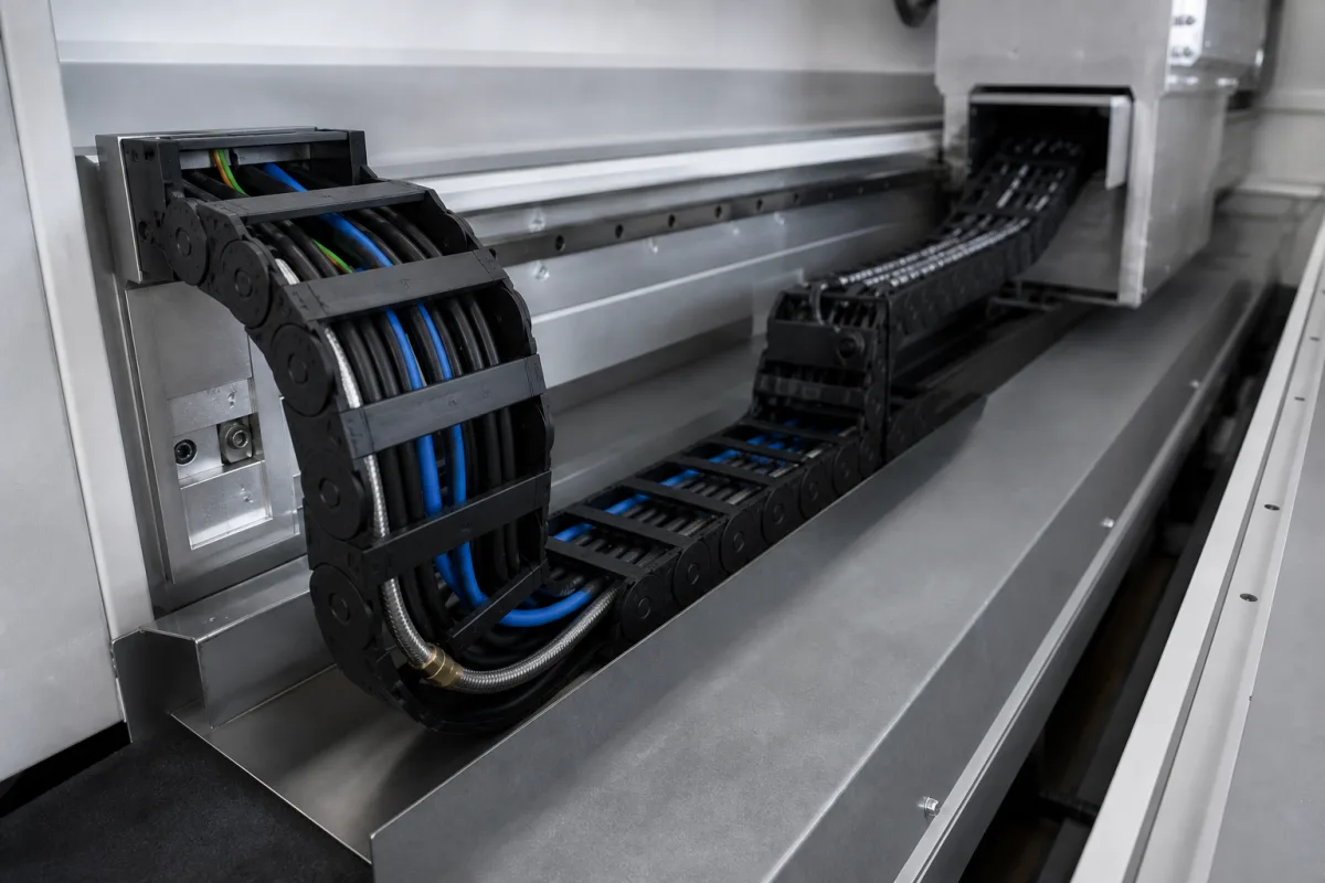
Representative product image. Confirm appearance and specifications with the manufacturer.

Product Specifications

Technical details and manufacturing context for Internal Cable Carrier

Definition
An internal cable carrier is a critical component within a robotic arm assembly, specifically designed to route and protect electrical cables, data lines, and pneumatic or hydraulic hoses that supply power, signals, and fluids to the arm's actuators, sensors, and end-effector. It is typically integrated into the arm's internal structure or joints to manage the repeated bending and flexing motions without causing wear, tangling, or failure of the internal lines, ensuring reliable operation and safety. The carrier consists of interlinked segments (links) that form a flexible, articulated chain. As the robotic arm articulates, these links pivot relative to each other, creating a controlled bending radius that guides the enclosed cables and hoses along a predictable, stress-minimized path. This prevents sharp bends, pinch points, and excessive tensile or torsional forces on the lines during the arm's range of motion. The carrier is available in engineering plastics (e.g., Nylon, POM) or stainless steel, with parameters such as inner height (15–60 mm), inner width (15–200 mm), bending radius (18–250 mm), travel length (10–100 m), maximum speed (5–20 m/s), maximum acceleration (10–50 m/s²), operating temperature (-40–85 °C), ingress protection (IP54–IP65 per IEC 60529), material grade (PA66, POM per UL 94), weight per meter (0.5–5.0 kg/m), tensile strength (50–200 MPa per ISO 527), and flammability rating (V0–V2 per UL 94). These values are reference ranges; verify model-specific specifications with the manufacturer. The carrier's design must accommodate the cable bundle diameter and the number and size of cables, and higher speeds may require special design. Exceeding maximum acceleration may cause vibration and wear. Operating outside the temperature range may cause material brittleness or deformation. For high-risk environments, a V0 flammability rating is required. The carrier is a component, not a complete system, and its selection depends on the robotic arm's geometry, motion profile, and environmental conditions. Regular inspection for wear, fatigue, and proper routing is recommended to maintain performance and safety.
Working Principle
The carrier consists of interlinked segments (links) that form a flexible, articulated chain. As the robotic arm articulates, these links pivot relative to each other, creating a controlled bending radius that guides the enclosed cables and hoses along a predictable, stress-minimized path. This prevents sharp bends, pinch points, and excessive tensile or torsional forces on the lines during the arm's range of motion.
Common Materials
Engineering Plastic (e.g., Nylon, POM), Stainless Steel
Technical Parameters
ParameterTypical rangeNotes & selection driver
Inner Height15–60 mmMust accommodate cable bundle diameter
Inner Width15–200 mmSelect based on number and size of cables
Bending Radius18–250 mmDetermines minimum bend of cables
Travel Length10–100 mMax unsupported length without guides
Maximum Speed5–20 m/sHigher speeds may require special design
Maximum Acceleration10–50 m/s²Exceeding may cause vibration and wear
Operating Temperature-40–85 °COutside range material may become brittle or deform
Ingress ProtectionIP54–IP65IP65 for dust-tight and water jet protectionIEC 60529
Material GradePA66, POMFlame retardant V0 availableUL 94
Weight per Meter0.5–5.0 kg/mAffects drive power and inertia
Tensile Strength50–200 MPaMinimum for cable pull forcesISO 527
Flammability RatingV0–V2V0 required for high-risk environmentsUL 94

Ranges are indicative industry figures for RFQ preparation, not a supplier commitment. Confirm every value and standard with the legal manufacturer before ordering.

Components / BOM
  • Link Part
    Individual segment that interlocks to form the flexible chain; houses and separates cables.
    Material: Engineering Plastic or Metal
  • Separator Part
    Internal insert that divides the carrier's interior into compartments to organize and isolate different cables/hoses.
    Material: Plastic
  • End Connector Part
    Attachment point that fixes the carrier to the robotic arm's static and moving structures.
    Material: Metal (e.g., Aluminum, Steel)

Applied To / Applications

This component is essential for the following industrial systems and equipment:

Industrial Ecosystem & Supply Chain Structure

Complementary Systems
Downstream Applications
Specialized Tooling

Application Fit & Sizing Matrix

Operational Limits
pressure: Not applicable (non-pressure containing system)
other spec: Bending radius: 5x to 10x carrier height, Acceleration: up to 10 m/s², Travel speed: up to 5 m/s, Fill capacity: 60-80% of cross-sectional area
temperature: -40°C to +120°C (continuous), up to +150°C (intermittent)
Media Compatibility
✓ Hydraulic hoses (SAE 100R series) ✓ Shielded robotic control cables (Cat6/7, EtherCAT) ✓ Flexible pneumatic tubing (PU/Nylon)
Unsuitable: High-pressure abrasive slurry transport (>50% solids concentration)
Sizing Data Required
  • Total cable/hose bundle diameter (mm)
  • Minimum required bending radius (mm)
  • Maximum travel length and acceleration profile (m, m/s²)

Reliability & Engineering Risk Analysis

Failure Mode & Root Cause
Cable carrier link fracture
Cause: Excessive bending radius beyond design limits, causing stress concentration and material fatigue
Internal cable abrasion
Cause: Insufficient cable slack management leading to rubbing against carrier edges during movement cycles
Maintenance Indicators
  • Audible grinding or scraping noises during carrier movement
  • Visible cracks or deformation in carrier links or hinge points
Engineering Tips
  • Install proper cable strain relief at both ends to prevent tension transfer to carrier links
  • Implement regular cleaning schedule to remove abrasive contaminants from carrier tracks and joints

Indicative industry ranges for design and RFQ preparation. Confirm the exact figures and applicable standard with the manufacturer before specifying.

Compliance & Manufacturing Standards

Applicable Standards
ISO 4400:1994 - Fluid power systems and components - Connectors and associated components - Nominal pressures ANSI/NFPA T3.6.7 R1-2015 - Fluid Power Standards - Cylinders - Bore and Rod Diameters and Tolerances DIN 2391-1:2016 - Precision steel tubes - Part 1: Seamless cold drawn tubes - Technical delivery conditions

Quoted from the published standard.

Manufacturing Precision
  • Bore diameter tolerance: +/-0.02 mm
  • Flatness tolerance: 0.1 mm per 100 mm length
Quality Inspection
  • Dye Penetrant Test for surface defects
  • Spectrographic Analysis for material composition verification

Manufacturers of Internal Cable Carrier

Manufacturer profiles associated with Internal Cable Carrier.

Sourcing Internal Cable Carrier from China?
Tell us your specification and target quantity — we will match it against manufacturer records and come back with the factories that fit.
Request manufacturers We manufacture this

Manufacturer listings support early research and capability understanding. They are not certification, ranking, or transaction guarantees.

Technical documentation
Request current drawings, revision history, and a signed specification sheet.
Manufacturing capability
Verify equipment lists, process limits, capacity, and representative production evidence.
Inspection readiness
Confirm test methods, calibrated equipment, sampling plans, and traceable reports.
Supplier transparency
Check the legal entity, factory address, ownership, certifications, and direct contacts.

CNFX does not score or rank suppliers. Buyers must verify all claims and documents with the legal manufacturer before ordering.

Supply Chain Compatible Machinery & Devices

Heavy-Duty CNC Plasma Cutting Machine

The Heavy-Duty CNC Plasma Cutting Machine is a standalone industrial device designed for cutting conductive metals such as steel, stainless steel, aluminum, and copper alloys.

Explore Specs →
Automated Powder Coating System

Integrated industrial system for applying dry powder coatings to metal substrates.

Explore Specs →
Centrifugal Pump Impeller

The centrifugal pump impeller is a critical rotating component that converts mechanical energy from the motor into kinetic energy in fluid systems.

Explore Specs →
High-Precision CNC Laser Cutting Machine

Computer-controlled industrial machine using focused laser beams to cut sheet metal with micron-level accuracy.

Explore Specs →

Frequently Asked Questions

What is the primary function of an internal cable carrier?

It organizes, guides, and shields cables and hoses within a robotic arm's moving joints, preventing wear, tangling, and failure during repeated bending and flexing.

What materials are available for internal cable carriers?

Engineering plastics such as Nylon or POM, and stainless steel. Material grade examples include PA66 and POM, with flammability ratings V0–V2 per UL 94.

What are the typical parameter ranges for internal cable carriers?

Inner height 15–60 mm, inner width 15–200 mm, bending radius 18–250 mm, travel length 10–100 m, maximum speed 5–20 m/s, maximum acceleration 10–50 m/s², operating temperature -40–85 °C, ingress protection IP54–IP65, weight per meter 0.5–5.0 kg/m, tensile strength 50–200 MPa. These are reference ranges; confirm with the manufacturer.

How should I verify that a cable carrier meets my application requirements?

Check the manufacturer's datasheet for model-specific values, and ensure the carrier's inner dimensions accommodate your cable bundle, the bending radius matches your arm's motion, and the speed/acceleration ratings are not exceeded. Also verify compliance with relevant standards such as IEC 60529 and UL 94.

Data Basis

Editorial classification, named public sources where available, and source-reviewed manufacturer records.

Preliminary Technical Classification
This page supports structured research, RFQ preparation, and supplier evaluation. It does not replace buyer-led supplier qualification, standards review, or technical approval.
Buyer enquiry

Request manufacturing insight for Internal Cable Carrier

Ask for use case, specification boundaries, supplier type, and RFQ preparation information for this product.

Where it goes
Straight to the CNFX editorial desk, and to the manufacturer if this product is linked to a claimed profile. Nothing is broadcast to a supplier list.
Your details stay here
We do not sell or rent enquiry data, and we do not add you to a mailing list. Used only to answer this request.
No commission, no middleman
CNFX is a directory. We take no cut of any order and never negotiate on a supplier's behalf.
What we don't claim
A listing is not an endorsement. Qualify every supplier and verify every figure yourself before ordering.

Your business information is used only to process this request.

Thank you! Your message has been sent. We'll respond within 1–3 business days.
Sorry, we couldn't send your message. Please try again, or email us at contact@cnfx.com.

Need to Manufacture Internal Cable Carrier?

Compare manufacturer profiles with relevant product and process capability.

Previous Product
Z-axis Ram/Spindle
Last Product
Get QuotesChat