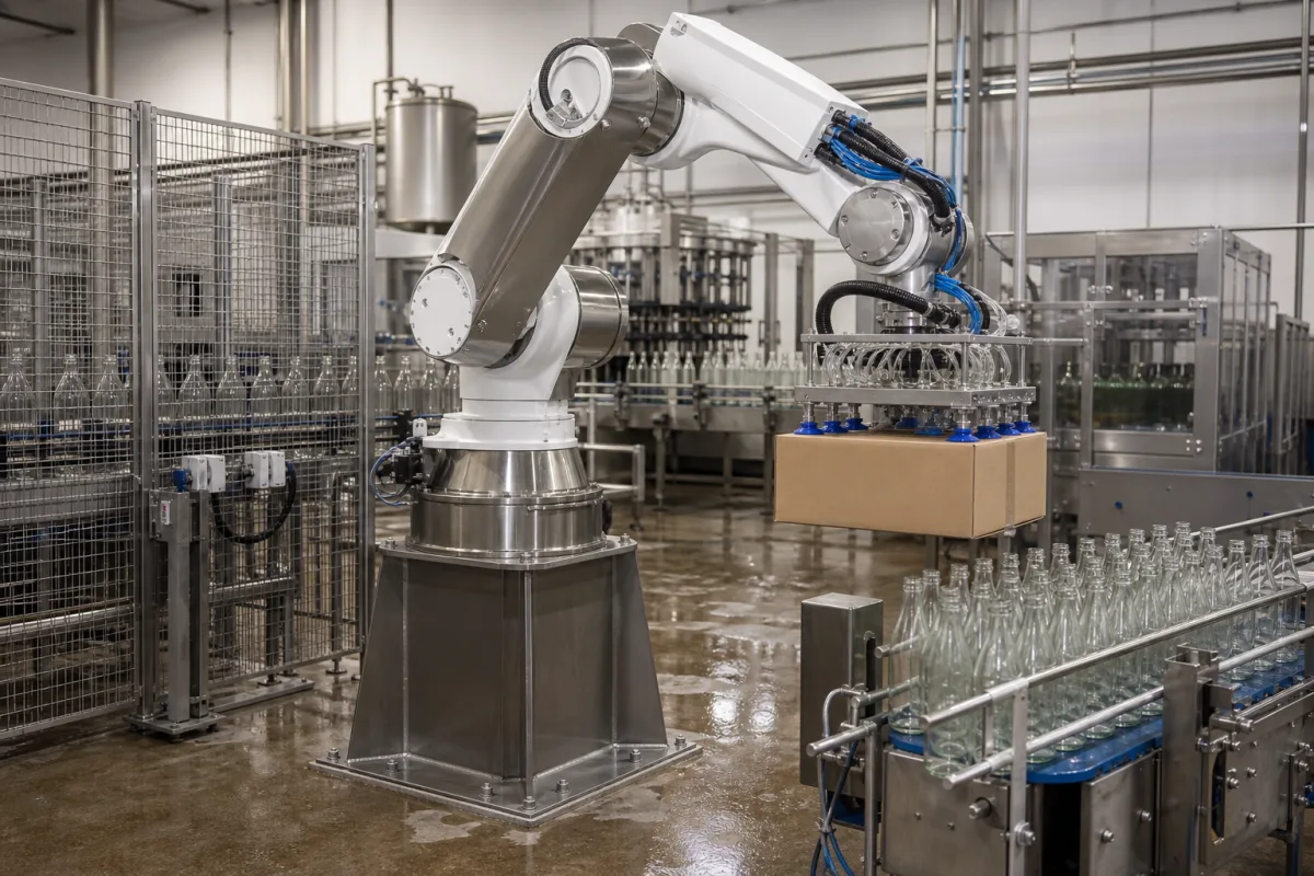
Robotic arm assembly for wet beverage and food packing areas: sealing by joint, cleaning regime and food-grade lubricant
The robot arm itself in a wet beverage or food packing hall · which joints an IP67 or IP69K rating covers, wipe-down against wash-down under a cover, and the 10 ppm limit behind food-grade lubricant
The arm in a bottling or packing hall is the same six-axis mechanism used elsewhere, but it stands on a wet floor, is splashed by product and rinse water, and has to be cleaned to the hygiene level of the area it works in. Before payload and reach, three questions decide whether an arm suits the job: which parts of it are sealed to which rating, whether it is meant to be wiped or hosed, and what lubricant is inside joints that sit above open product.
Articulated robot arms (the arm, wrist and tool flange as a mechanical assembly) chosen for wet beverage and food packing areas: ingress protection by body region, stainless tool flanges, wipe-down and wash-down cleaning regimes, protective covers and food-grade lubrication. Complete palletizing cells for beverage packs are covered on the Automated beverage container palletizing system page and depalletizers on the Automated beverage container depalletizing machine page; sizing an arm by wrist load, moment and reach is covered on the Robotic manipulator page.
CNFX editorial research · Sources checked October 13, 2026 · 3 sources
IP67 body, IP69K flange, IP54 standard: what each arm's rating covers
A single IP figure on a datasheet can refer to the whole arm or to one part of it. Two published arms show the difference. [1][2]
ABB limits its IP69K claim to the axis-6 flange and gives a 30 bar ceiling; FANUC's IP67 for the body is an option, not the standard build. [1][2] Editorial note: a case of filled bottles plus a vacuum head can exceed the 5 to 7 kg the small hygienic arm carries; where it does, the arm comes from a heavier class like the 50 kg FANUC, and the order has to name the IP67 option explicitly rather than assume it.
State which zones of the arm will be splashed or sprayed, the maximum cleaning pressure and temperature, and ask for the IP rating of body, wrist and flange separately.
02
Wipe-down in low-care areas, wash-down under a cover in high-care areas
ABB offers its hygienic arm for two cleaning regimes: wipe-down cleaning for low-care food packaging environments, and wash-down cleaning with the robot fitted with a protection cover for high-care food processing and packing. [1]
For wipe-down, ABB specifies cleaning with a specified wipe-down detergent and a lint-free cloth. It lists meat, poultry, fish, fruits, vegetables and dairy among the products the arm is designed to handle, and primary packaging among its uses. [1]
Editorial note: the pictured cell, with a wet floor beside a bottle conveyor and filler, sits between the two regimes; whether the area is hosed down at the end of a shift, and with which chemicals, decides whether a cover and a higher-rated flange are needed. Ask the robot maker for the list of approved detergents and sanitisers and their concentration, since that list, not the IP code, defines what the arm will tolerate.
Describe the hygiene zone (low-care, high-care or dry), how and how often the area is cleaned, the chemicals and their concentration, and whether a protective cover is acceptable.
03
Lubricant above open product: the 21 CFR 178.3570 limits and NSF H1 oil in the joints
In the United States, lubricants with incidental food contact on food-processing machinery are governed by 21 CFR 178.3570. The rule covers use as a lubricant for machine parts where the lubricated part is exposed to food, requires the minimum amount needed for the technical effect, and caps what each listed constituent may add to food. [3]
ABB states that its hygienic arm uses NSF H1 food-grade oil throughout. [1] FANUC's M-710iC/50 specification lists protection classes but no lubricant grade, so for an arm working over open containers the lubricant has to be asked for. [2]
Editorial note: the regulation sets limits on what reaches food, not on how a robot is built; the buyer still has to confirm with the robot maker which grease and oil are in each joint, their registration and the relubrication interval.
Ask for the lubricant in every joint and gearbox, its food-contact registration, and whether open containers pass under the arm.
04
What to send for a robot arm in a wet packing area
Paste it into your enquiry below or into an email to a maker, then replace every bracket.
Task: [product handled; case or container mass; gripper type]
Area: [hygiene zone; splash or hose-down; open product under the arm]
Cleaning: [method; pressure; temperature; chemicals and concentration]
Protection: [IP rating required for body, wrist and flange; cover]
Lubricant: [food-grade grade and registration per joint]
Arm: [payload; reach; mounting; repeatability]
Explore company information and manufacturing capabilities, then discuss the scope of your project with a relevant supplier.
Share this page
Compiled and source-reviewed by the CNFX editorial team.
Each manufacturer above links to the page on that company's own website where the product is listed, with the date we checked it. How we source and review
· Page last updated 13 October 2026
Buyer questions
Does an IP69K robot have IP69K on every joint?
Not necessarily: ABB's IRB 1200 Hygienic is IP67 on the body and IP69K (max. 30 bar) only on the stainless axis-6 flange. [1]
Is a heavy-payload robot sealed for washdown as standard?
FANUC lists the M-710iC/50 body as IP54 standard with IP67 as an option, and the wrist and J3 arm as IP67. [2]
How much lubricant may reach food from machinery?
21 CFR 178.3570 limits mineral oil from incidental-contact lubricants to 10 ppm in food and dimethylpolysiloxane to 1 ppm, and requires the minimum amount needed. [3]
Sources and what still needs a direct check
Sources checked 2026-10-13. Hygienic arm data come from ABB's IRB 1200 Hygienic page; heavy-arm protection classes from FANUC America's M-710iC/50 specification; lubricant limits from the US eCFR text of 21 CFR 178.3570.