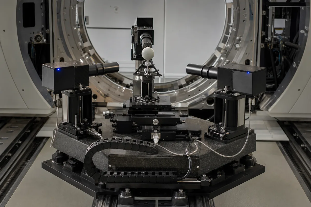
Laser alignment verification for radiotherapy rooms: ball-bearing isocentre targets and camera checkers that test the room lasers against the beam
Radiotherapy QA tooling · checking that the room lasers and cross-hairs point at the radiation isocentre, with a ball-bearing target or a camera that reads the laser lines
Every patient set-up in an external-beam room starts at the wall and ceiling lasers: the patient's skin marks are lined up on the laser cross, and the couch is then shifted from there. If the lasers do not cross at the radiation isocentre, every set-up carries that offset into treatment until imaging catches it. A laser alignment verification device is the tool that measures the offset. It is either a radiopaque target that is first placed on the lasers and then imaged with the beam, or an optical system that photographs where the laser lines land on a calibrated surface and compares them with the light field and the radiation field.
Verification tools for radiotherapy room lasers and their coincidence with the radiation isocentre: ball-bearing Winston-Lutz targets and stages, multi-insert QA phantoms with laser alignment lines, and camera-based checkers that read laser and cross-hair positions on a marked or phosphor-coated surface. The complete accelerator is covered on the Medical linear accelerator page; couch rotation about the isocentre is covered on the Treatment Table page, and couches themselves on the Six-degree-of-freedom radiotherapy treatment couch and Radiotherapy patient positioning couch pages; the treatment console is covered on the Centralized control system page. The room lasers sold as instruments, CT-simulator lasers and dosimetry phantoms used only for dose are outside this page.
CNFX editorial research · Sources checked October 13, 2026 · 5 sources
How far the laser cross may sit from isocentre: 1 mm tolerance and 2 mm action level in CPQR, against a 1.5 mm IMRT figure attributed to TG-142
A verification device is only useful if it resolves well inside the tolerance it is checking. The published limits for the daily laser and cross-hair check differ by guideline, and the buyer should know which one the department works to before choosing a target or camera.
Editorial calculation: a device that can only resolve 0.5 mm uses half of CPQR's 1 mm tolerance on its own reading. [1] The tools further down this page report 0.1 mm to 0.25 mm per image pixel, which leaves room inside a 1 mm limit. [4][5]
Guideline or study
Laser / isocentre figure
Context
Canadian Partnership for Quality Radiotherapy (CPQR) technical QC guideline
Tolerance 1 mm, action level 2 mm for the daily laser/cross-hair check [1]
Stated in COMP's reply to a reviewer during the guideline review [1]
The reviewer asked whether the TG-142 IMRT figure had been considered; CPQR kept its 1 mm / 2 mm levels [1]
RUBY phantom study, New Delhi
Displacements judged against a maximum deviation of 1 mm in any direction; Winston-Lutz deviations of 0.4 mm or less [3]
TrueBeam STx with HD MLC; SRS and SRT programme [3]
Write the tolerance and action level the device must report against (for example 1 mm and 2 mm), the beam modalities and SRS/SBRT use, and whether results must trend over time or only pass/fail.
02
Ball-bearing targets: a 6.5 mm tungsten ball set on the lasers to within ±2 mm, then located to 0.1 mm with paired collimator angles
The ball-bearing method uses the lasers only to place the target; the beam then tells where the target really sits. The difference between the laser-set position and the radiation isocentre is the laser error.
MD Anderson's study used a tungsten ball 6.5 mm in diameter glued on an acrylic rod screwed into an acrylic base block, positioned near isocentre (within ±2 mm) with the room lasers, and imaged on TrueBeam linacs with an aS1200 EPID whose 0.336 mm pixel scales to 0.224 mm at isocentre. [2] Using a single collimator angle produced errors of as much as 0.4 mm in the computed radiation isocentre; opposite or mixed collimator angles brought the error below 0.1 mm, and isocentres varied by less than 0.1 mm across field sizes from 2 × 2 cm² to 20 × 20 cm². [2] Between collimator 0° and 90°/270° the study saw a difference of about 0.2 mm in y on all four linacs. [2]
The RUBY phantom study set its Winston-Lutz insert, a centrally embedded ceramic ball, on the room lasers first, then imaged at gantry and collimator angles from 0° to 315° in 45° steps; couch rotations gave the largest shifts, with −0.4 mm in x and +0.2 mm in y at 45° and +0.3 mm in x at 315°, and the authors report that after automatic couch correction the phantom's black alignment line coincided with the room lasers. [3] The same paper describes the Lucy phantom as having manufacturing tolerances of about 0.1 mm. [3]
Editorial calculation: eight gantry angles plus eight collimator angles at 45° spacing, as in the RUBY test, is 16 images before any couch angles are added (8 + 8). [3]
Ask for the ball material and diameter, how the ball is adjusted (fixed rod or micrometre XYZ stage, and its step size), the marks used for laser set-up, which collimator angles the analysis software combines, and the EPID or film the analysis expects.
03
Camera checkers: 0.28 mm raw pixels resampled to 0.10 mm on a 12.5 cm phosphor cube, and a 2448 × 2048 camera read at 0.25 mm per pixel
Optical checkers photograph where the laser lines and cross-hairs fall and measure them in software, so the reading no longer depends on who looks at the graph paper. Two published systems show the numbers a buyer can ask for:
The Stanford group tested its system by writing deliberate 1–2 mm misalignments into the delivery file; a 1.0 mm shift of the X1 collimator was measured as 1.4 mm on the field, and individual collimator perturbations were measured with an average error of 0.13 mm. [4] Mayo's team found over five years of use that room lighting had to be fixed per vault for reproducible results, and that camera calibration must be repeated after any change to lens aperture or focus. [5]
Editorial calculation: at 0.28 mm per raw pixel a 1 mm laser tolerance spans about 3.6 pixels (1 ÷ 0.28); at Mayo's 0.25 mm per pixel the 2000-pixel transformed image covers 500 mm, enough for the 40 × 40 cm field it was built to capture (2000 × 0.25). [4][5]
Item
Stanford radioluminescent phantom system
Mayo Clinic CVQA
Target
3D-printed cube 12.5 cm on each side, coated with Gd₂O₂S:Tb in PDMS, with 2.4 mm steel balls as fiducials [4]
Marker board with four 30 mm ArUco markers, outer corners 180 mm apart, centred on the cross-hair marks [5]
Camera
1280 × 960 pixel CMOS camera on the accessory tray, 5 mm f/2.5 lens [4]
Blackfly S GigE camera with 8.5 mm lens on a 3D-printed mount in the interface mount [5]
Scale
0.28 mm per raw pixel, resampled to 0.10 mm per pixel after self-calibration [4]
2448 × 2048 raw image, transformed to 2000 × 2000 pixels at 0.25 mm per pixel [5]
Laser test
Distance between the centre of the laser cross-hairs and the light-field cross-hairs [4]
Laser test not in its list; field sizes, angles, walkout, couch travel and ODI [5]
Repeatability and time
Standard deviation on the order of 0.1 mm; about 10 minutes for set-up, delivery and report [4]
Within 0.5 mm and 0.5°; ODI within 1 mm; 5 min set-up and 7 min for all tests [5]
For a camera system, ask for the pixel scale on the target plane, the calibration target and how often calibration is repeated, the lighting conditions it was validated under, and how it reports the laser-to-cross-hair distance.
04
Details to give for a laser alignment verification device
Paste it into your enquiry below or into an email to a maker, then replace every bracket.
Linac model and accessory/interface mount: [ ]
Tolerance and action level to report: [mm]
Method: [ball-bearing target; multi-insert phantom; camera checker]
Target: [ball material and diameter; stage adjustment step]
Imaging: [EPID model; film; camera]
Tests needed: [laser to cross-hair; laser to radiation isocentre; couch angles]
Output: [pass/fail; trend database; report format]
Explore company information and manufacturing capabilities, then discuss the scope of your project with a relevant supplier.
Share this page
Compiled and source-reviewed by the CNFX editorial team.
Each manufacturer above links to the page on that company's own website where the product is listed, with the date we checked it. How we source and review
· Page last updated 13 October 2026
Buyer questions
What tolerance applies to radiotherapy room lasers?
The CPQR guideline sets a 1 mm tolerance and 2 mm action level for the daily laser/cross-hair check; a reviewer of that guideline cited 1.5 mm for IMRT from TG-142. [1]
How precisely can a Winston-Lutz ball test locate the radiation isocentre?
An MD Anderson study reached 0.1 mm using opposite or mixed collimator angles; a single collimator angle gave errors of up to 0.4 mm. [2]
Can a camera check the room lasers automatically?
Yes. A Stanford system imaged lasers, light field and radiation field on a phosphor-coated cube at 0.10 mm per calibrated pixel and completed its tests in about 10 minutes. [4]
How is the ball target first positioned?
On the room lasers: MD Anderson placed its 6.5 mm tungsten ball within ±2 mm of isocentre this way before imaging it with the beam. [2][3]
Sources and what still needs a direct check
Sources checked 2026-10-13. Five peer-reviewed papers: COMP's account of the CPQR quality-control guideline review, MD Anderson's Winston-Lutz precision study, a New Delhi evaluation of the RUBY phantom, and the Stanford and Mayo Clinic camera-based QA systems.