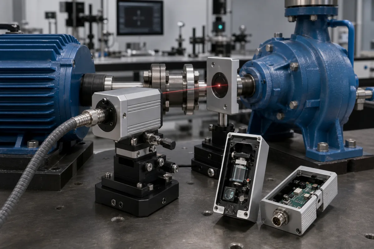
Laser alignment module for shaft alignment: the measuring heads that put a beam and a position-sensitive detector across a coupling
The emitter-and-detector heads clamped either side of a coupling · two-head PSD units versus a single laser with a reflecting prism, detector size, accuracy over distance, and the laser data on the label
A laser alignment module, in shaft alignment, is a measuring head that clamps to one shaft and either emits a laser beam across the coupling or detects where a beam lands. Rotating both shafts together moves the spot on the detector, and the display unit turns that movement into offset and angle at the coupling and shim and move values at the machine feet. What separates one module from another is how many heads carry a laser, how big and fine the detector is, how far apart the heads can be, and how the laser is classified.
Laser measuring units (emitter, detector, or combined emitter-detector heads, and the reflecting prism of single-laser systems) for aligning coupled rotating shafts of motors, pumps, fans and gearboxes, as bought with or for a shaft alignment system. Fibre-coupled and free-space laser diode modules sold as light sources are covered on the Laser diode module page. Pipe lasers for trench and sewer grade are covered on the Laser guidance system for pipe laying page, and camera-module lens alignment machines on the Active optical alignment station page. Couplings themselves are covered on the Shaft coupling page, and motor-coupling-base packages on the Direct-coupled fan motor assembly page; laser trackers, geometric alignment of rolls and bores, and dial-indicator kits are outside this page.
CNFX editorial research · Sources checked October 12, 2026 · 3 sources
Two PSD heads facing each other, or one laser head and a 90° roof prism
Two layouts appear in the data sheets reviewed. In the first, a measuring unit on each shaft carries its own laser and detector: Easy-Laser's XT40 is sold as an M-unit and an S-unit, each with a 30 mm TruePSD and a laser, and each with an OLED display showing the angle of the unit. [1] The Shaft Hog brochure likewise lists measuring units with single-axis PSD detectors and a diode laser, joined to the display unit by 1.6 m cables. [2]
In the second layout, a single sensor sends the beam and reads it back. Fluke's 830 states its measurement principle as a coaxial, reflected laser beam: the sensor carries a Ga-Al-As semiconductor laser and the detector, and the opposite shaft carries a 90° roof prism weighing 65 g. Fluke describes the detector measurement area as unlimited and dynamically extendible under US Patent 6,040,903, and markets an extend mode for gross misalignment. [3]
Editorial note: with two heads, each unit's laser, detector and battery have to be serviced and calibrated; with a prism layout, only the sensor is electronic, but the prism face has to stay clean and square to the beam. Ask the supplier which layout the module belongs to before buying a spare head, since a head from one layout is not a spare for the other unless the supplier confirms it.
Name the system the module must work with, whether you need the stationary or movable head (M or S), and whether the replacement must match the existing cable or wireless link.
02
Detector size, resolution and accuracy against the distance between heads
The detector sets how much misalignment the heads can read before the spot leaves the active area, and the stated accuracy is quoted differently by each maker.
Editorial calculation: the Shaft Hog's ±0.00039 in is about ±9.9 µm (0.00039 × 25.4 mm). For the XT40, reading ±1 µm ±1% literally, a 0.50 mm reading would carry about ±6 µm (1 µm plus 1% of 500 µm); ask Easy-Laser whether the 1% applies to the reading or to the range. [2][1]
The Easy-Laser page gives a resolution (±0.005 mm +1%) coarser than its stated accuracy (±1 µm ±1%), which is unusual; confirm both figures against the calibration certificate for the units you receive. [1]
State the largest coupling-to-coupling distance on your machines and the largest offset you expect before correction; both decide whether a 30 mm detector, a single-axis PSD within 850 mm, or an extendible-area sensor is enough.
03
Laser class, wavelength and pulse data printed on the head
All three heads are class 2 visible red lasers, but the data published for them differ in depth.
Editorial calculation: at the XT40's maximum pulse energy of 8 nJ and 75 kHz repetition rate, the average works out to 0.6 mW (8 nJ × 75,000 per second), matching the stated maximum average power; at 120 kHz the same pulse energy would give about 0.96 mW, so the 8 nJ and 120 kHz limits are not reached together under the 0.6 mW cap. [1] The 200 mrad divergence in one axis is a fan, not a round spot.
For import or site safety files, ask for the laser class label text, the standard it was classified to, and the wavelength and power stated on it.
04
Housing, sealing and temperature ranges of the heads
Easy-Laser lists the XT40 housing as anodized aluminium with PC/ABS and TPE, IP 66 and 67, operation from −10 to 50 °C, 10–95% relative humidity, 76 × 76.7 × 39.3 mm and 245 g, with a 3.7 V, 2000 mAh lithium-ion battery giving up to 24 h. [1] The Shaft Hog measuring units have ABS plastic housings, and the system is rated 0 to 60 °C in non-condensing humidity. [2] Fluke rates its 830 sensor IP 67, 0 to 55 °C in operation, 107 × 70 × 49 mm and 177 g. [3]
Editorial note: on wet pump bases or outdoor cooling-tower drives, the sealing class and the lower operating temperature limit decide more than the detector figures; check both against the site.
05
Head type, distance and laser data for a shaft alignment module
Paste it into your enquiry below or into an email to a maker, then replace every bracket.
System: [make and model the module must work with; M or S head; or prism]
Link: [cable length or wireless]
Machines: [shaft diameters; largest distance between heads; expected offset]
Detector: [type; active size; resolution; accuracy statement and basis]
Laser: [wavelength; power; class and standard]
Environment: [IP rating; operating temperature; humidity]
Documents: [calibration certificate; laser class label]
Explore company information and manufacturing capabilities, then discuss the scope of your project with a relevant supplier.
Share this page
Compiled and source-reviewed by the CNFX editorial team.
Each manufacturer above links to the page on that company's own website where the product is listed, with the date we checked it. How we source and review
· Page last updated 13 October 2026
Buyer questions
What does a laser alignment module measure?
Where a laser spot lands on a position-sensitive detector as the shafts are turned; Easy-Laser's XT40 heads use a 30 mm PSD and an inclinometer to read the unit angle. [1]
Do all shaft alignment systems use two laser heads?
No. Fluke's 830 uses one sensor and a 90° roof prism with a coaxial, reflected beam, while the XT40 and Shaft Hog put a unit on each shaft. [3][1][2]
How far apart can the heads be?
Easy-Laser gives a measurement range up to 10 m for the XT40; the Shaft Hog brochure gives a maximum of 850 mm between measuring units. [1][2]
What laser class are shaft alignment heads?
All three reviewed are class 2: 630–680 nm under 0.6 mW (XT40), 670–675 nm at most 1 mW (Shaft Hog), 675 nm (Fluke 830). [1][2][3]
Sources and what still needs a direct check
Sources checked 2026-10-12. Three maker or seller documents: Easy-Laser's XT40 technical data page from its user manual, Newman Tools' Shaft Hog brochure, and Fluke's 830 specification page.