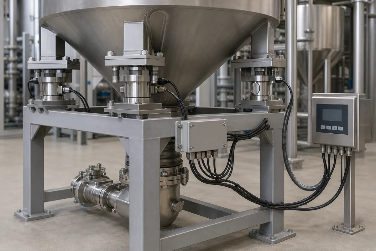
Hopper and vessel weighing installation: pipe forces, mounting and corner trimming that decide whether the load cells read true
Installing load cells under a hopper or vessel · the force attached pipes put on the scale, three supports at 120°, stay rods and lift-off protection, corner trimming at the summing box, and calibration with real weights
Good load cells under a hopper can still read wrong. The vessel moves down a fraction of a millimetre as it fills, and every pipe, conduit, ladder or stay rod tied to it can push back; temperature, pressure and wind add their own forces; and each cell's output differs slightly from the next. A load-cell system for a process vessel is therefore as much an installation as a set of sensors — mounts, connections, restraints, junction-box trimming and calibration all decide the accuracy.
Load-cell weighing systems installed under process hoppers, tanks and vessels: mounting arrangement and weigh modules, attached piping and flexible connections, restraints, pressure effects, corner trimming in the summing junction box, and calibration. Sizing load-cell capacity, accuracy classes and shear-beam construction for tank and hopper scales are covered on the Load cell scale page; load cells themselves on the Precision load cell page; indicators on the Weight indicator / controller page; loss-in-weight and weighed-hopper dosing on the Beverage ingredient dosing station page; portable load-cell calibration kits on the Portable calibration module for load cells and 4–20 mA loops page.
CNFX editorial research · Sources checked October 12, 2026 · 3 sources
Attached pipes push back: Rice Lake's force formula and the 0.1 × accuracy × live-load limit
Rice Lake Weighing Systems' load cell and weigh module handbook calls attached piping by far the largest source of error in vessel weighing. When the vessel fills it moves down by the load-cell deflection — 0.005 to 0.015 in at full load — plus the deflection of the support structure, and a horizontal pipe held at its first support pushes back by F₁ = 0.59 (D⁴ − d⁴) × Δh × E ÷ l³. [1] Its worked example on a 4 in schedule 40 steel pipe shows what changes the force:
Rice Lake gives the scale industry's acceptance rule as the sum of all vertical pipe forces F ≤ 0.1 × system accuracy (%) × live load; for a 50,000 lb live load at 0.25% that is 1,250 lb. Its rules of thumb: stiffen the support structure, use the smallest and lightest-wall pipe, run pipes horizontally away from the vessel, and place the first support 20 to 30 pipe diameters away — at least 40 in, preferably 60 in, for a 2 in pipe. [1] Because the force grows with l⁻³, doubling the span cuts it to one-eighth, which is the 87% in the table. [1]
A process engineer writing in IChemE's The Chemical Engineer takes a slightly different line on hoses and bellows: in his words, “adequate flexibility is usually obtainable with careful routing and support of the piping”, with bending moments calculated between the connection and the nearest rigid support. [3]
Editorial calculation: for a hopper with a 2,000 kg (about 4,410 lb) live load weighed to 0.5%, Rice Lake's rule allows 0.1 × 0.5 × 4,410 ≈ 220 lb (about 100 kg) of total vertical pipe force — less than a fiftieth of the 13,840 lb in its first example.
Give the weighing supplier the live load, required system accuracy, every pipe, hose, conduit and cable attached to the vessel (size, schedule, material, span to first support) and the support-structure deflection under load.
02
Three supports at 120°, stay rods with lift-off protection, and bellows only within tight tolerances
HBM's guide to the structural design of tank weighing systems says the optimum is a tank resting on three bearing points, each with a load cell, equally distant from the vertical axis and 120° apart; four or more points make the bearing statically redundant, every point must then carry a load cell, and equal sharing can only be set during assembly by measuring each cell and shimming. [2] If the centre of gravity moves sideways as the vessel fills, all supports must have load cells. [2]
For supply connections HBM ranks the options: a long horizontal pipe acts as a vertical spring; a series of pliable couplings, or hoses of compatible elastic material work well; a pipe elbow helps; metal bellows suit vertical connections but need strict installation tolerances, and two bellows joined by a pipe section accept larger tolerances; an open filling stud that does not touch the tank is best where the system is not closed. HBM notes that metal bellows are not permitted in some cleaning-intensive food areas. [2] Rice Lake adds that neither hoses nor bellows should be used to take up an initial pipe offset. [1]
Pressure matters on closed vessels: HBM gives 100–300 mbar of negative pressure in extraction plants for powders, and on a vertical connection the error equals the pressure times the pipe's cross-sectional area; a horizontal layout lets the supports absorb it. Material in connected lines also counts as weight, so those lines should be always full or always empty when weighing. [2] Editorial calculation: 200 mbar (20 kPa) acting on a 100 mm bore (0.00785 m²) is about 157 N, roughly 16 kg of apparent weight change.
HBM's weigh-module example uses integrated stay rods tangential to the vessel and a built-in anti-lift-off device, at the cost of careful alignment of parallel contact surfaces and heights; Rice Lake's modules use a safety check screw through a clearance hole that prevents lift-off and doubles as a jacking screw for load-cell replacement. [2][1]
State how many supports the vessel has, whether its centre of gravity stays on one vertical line, the connections and their type (hose, bellows, open stud), operating pressure or vacuum, and the restraint required against tipping, wind or agitation.
03
Corner trimming at the summing junction box: excitation or signal trim, and when matched cells make it unnecessary
A summing junction box wires the cells' signal and excitation lines in parallel so the indicator reads one system signal. Rice Lake says trimming at the box is needed for legal-for-trade use, when the contents' centre of gravity is not fixed (powder piling to one side), or for high accuracy; it is not needed with matched-output cells or for self-levelling liquids. [1]
In excitation trim, a potentiometer in each cell's excitation lead lowers the voltage to the cells with higher mV/V so that all full-load outputs match the lowest; Rice Lake's example set reads 2.997, 3.003, 2.999 and 3.002 mV/V, with cell 1 as the reference at full excitation. [1] The handbook's matched-output weigh-module kits hold cell outputs to ±0.07%, which it says removes corner trimming at installation and after replacing a cell. [1]
Editorial calculation: 3.003 ÷ 2.997 ≈ 1.002, so without trimming the highest cell in that set reads about 0.2% more than the lowest for the same load — the same order as a 0.25% system accuracy target.
Ask whether the cells are output-matched, which trim method the junction box uses, and how corner tests will be done with the weights available.
04
Calibrating with weights, not a simulator, and in steps when the weights are light
Rice Lake states that calibration with real weight compensates for the residual effect of attached piping, whereas a load-cell simulator cannot, because it has no way to reproduce the piping forces. [1] Its installation guidelines also call for hanging weights from the vessel corners to trim the load-cell outputs when calibrating. [1]
The Chemical Engineer article recommends attachment points for hanging test weights, or a top surface for standard weights. Where the weights are less than the full load it describes stepwise calibration — weights on, record, weights off, add water to the same reading, weights on again — and warns that each water step carries the load cells' own error into the next, so the method adds error. [3]
Specify the calibration method (full test weights, build-up with substitution material, or reference material), the weight available, the attachment points on the vessel, and the acceptance tolerance.
05
What to send for a hopper or vessel load-cell system
Paste it into your enquiry below or into an email to a maker, then replace every bracket.
Vessel: [empty weight; live load; supports; centre of gravity fixed or moving]
Accuracy: [system accuracy %; legal-for-trade or process]
Connections: [each pipe, hose, conduit, cable — size, schedule, span to first support]
Conditions: [pressure or vacuum; temperature swing; agitation; wind or seismic]
Mounting: [weigh module type; stay rods; lift-off protection]
Electronics: [summing box trim method; indicator]
Calibration: [test weights or build-up; attachment points]
Explore company information and manufacturing capabilities, then discuss the scope of your project with a relevant supplier.
Share this page
Compiled and source-reviewed by the CNFX editorial team.
Each manufacturer above links to the page on that company's own website where the product is listed, with the date we checked it. How we source and review
· Page last updated 13 October 2026
Buyer questions
What is the biggest source of error in vessel weighing?
Rice Lake's handbook names attached piping; the vertical pipe forces should total no more than 0.1 × system accuracy (%) × live load. [1]
How many load cells should a hopper have?
HBM's optimum is three supports 120° apart, each on a load cell; with four or more, every support needs a cell and the loads must be balanced during assembly. [2]
When is corner trimming needed?
Rice Lake lists legal-for-trade use, a shifting centre of gravity and high accuracy; matched-output cells or liquid contents can make it unnecessary. [1]
Can a load-cell simulator replace test weights?
Not for a vessel with attached piping: Rice Lake notes a simulator cannot reproduce the piping forces. [1]
Sources and what still needs a direct check
Sources checked 2026-10-12. Pipe-force formula, examples, piping rules, trimming and calibration come from Rice Lake Weighing Systems' load cell and weigh module handbook; support arrangement, connection types and pressure effects from HBM's guide to the structural design of tank weighing systems; routing and stepwise calibration from an IChemE The Chemical Engineer rules-of-thumb article.