Editorial Technical Reference

Machine Bed & Column

This page explains how Machine Bed & Column is classified within Machinery and Equipment Manufacturing. Technical values and manufacturer relationships are research references; confirm the current specification and supplier evidence for each order.

Technical Definition & Core Assembly

The foundational structural assembly that provides rigidity, stability, and precision guidance for the multi-axis CNC machining center.

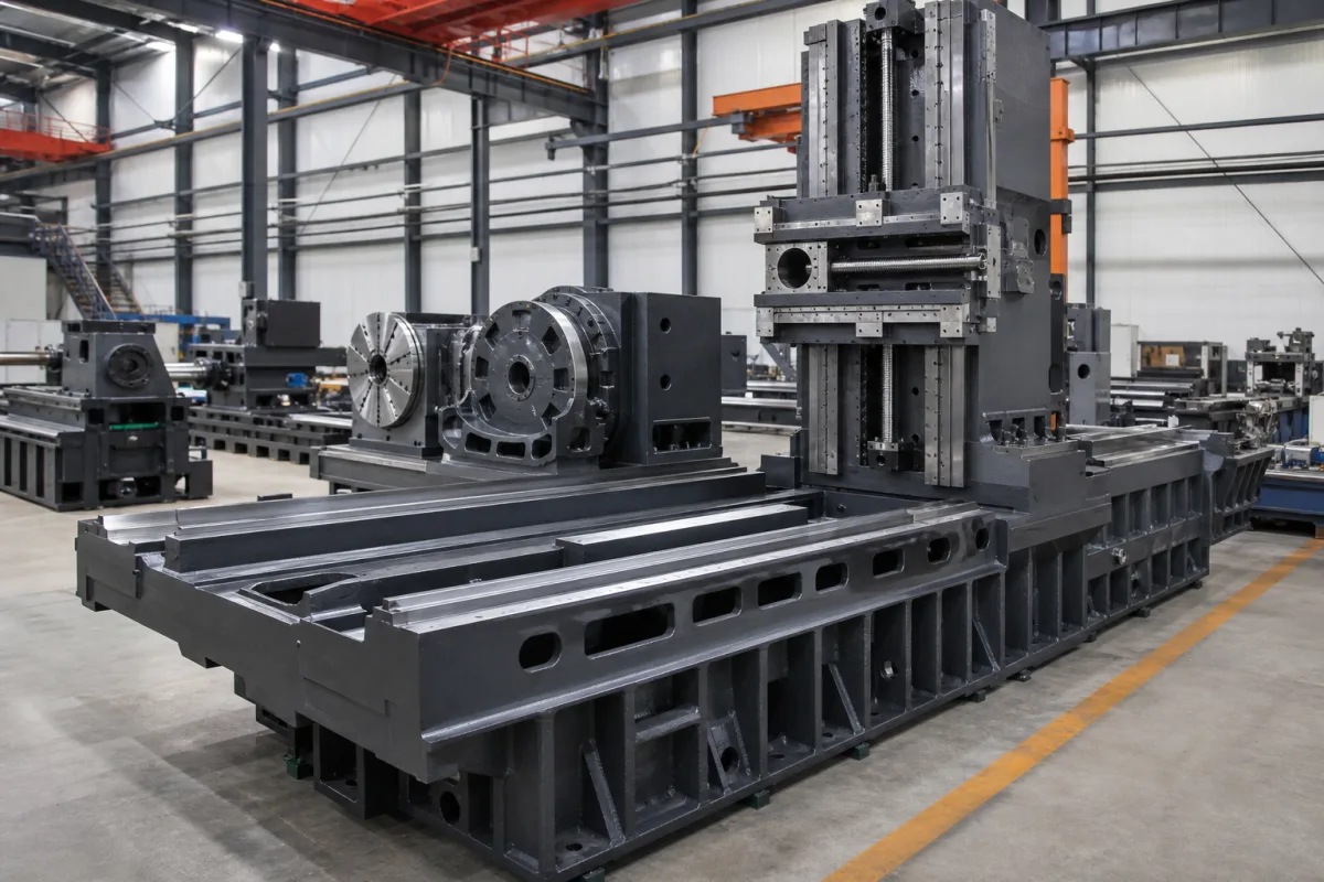
Representative product image. Confirm appearance and specifications with the manufacturer.

Product Specifications

Technical details and manufacturing context for Machine Bed & Column

Definition
The Machine Bed & Column forms the core structural framework of the Heavy-Duty Aluminum Profile Multi-Axis CNC Machining Center. The bed serves as the stable, vibration-dampening base that supports all other components and absorbs cutting forces. The column, mounted vertically on the bed, provides the rigid vertical axis for the spindle head and other moving elements. Together, they ensure the geometric accuracy, thermal stability, and dynamic stiffness required for high-precision, heavy-duty machining of aluminum profiles and other materials across multiple axes.

Constructed from materials such as cast iron (e.g., Mechanite, Gray Iron), mineral casting (polymer concrete), or welded steel, the bed and column are engineered to maximize static and dynamic stiffness. The bed is typically a massive, ribbed casting or welded structure designed to minimize deflection under load. The column is engineered to resist bending and torsional forces. Both components work in unison to provide a stable, non-deforming reference frame. Linear guideways or hardened ways are mounted on their surfaces to allow precise, low-friction movement of the machine's slides and carriages.

Key parameters for selection include worktable width (500–1200 mm), worktable length (1000–3000 mm), max load capacity (1000–5000 kg), positioning accuracy (±0.005–±0.02 mm per ISO 230-2), repeatability (±0.003–±0.01 mm per ISO 230-2), flatness (0.01–0.03 mm/m per ISO 1101), guideway straightness (0.005–0.02 mm/m per ISO 230-1), material grade (HT250–HT300 per GB/T 9439), heat treatment (600–700 °C), operating temperature (5–45 °C), relative humidity (35–85%), and machine weight (3000–15000 kg). These values are reference ranges and must be verified for the specific model and application with the legal manufacturer or supplier. Standards listed are procurement references, not certifications of compliance.
Working Principle
The bed is designed as a massive, ribbed casting or welded structure to maximize static and dynamic stiffness, minimizing deflection under load. The column is engineered to resist bending and torsional forces. Both components work in unison to provide a stable, non-deforming reference frame. Linear guideways or hardened ways are mounted on their surfaces to allow precise, low-friction movement of the machine's slides and carriages. Their inherent rigidity ensures that cutting forces are absorbed without causing chatter or positional errors, maintaining the programmed tool path accuracy.
Common Materials
Cast Iron (e.g., Mechanite, Gray Iron), Mineral Casting (Polymer Concrete), Welded Steel
Technical Parameters
ParameterTypical rangeNotes & selection driver
Worktable Width500–1200 mmDetermines max workpiece width
Worktable Length1000–3000 mmDetermines max workpiece length
Max Load Capacity1000–5000 kgExceeding may cause deflection
Positioning Accuracy±0.005–±0.02 mmCritical for machining toleranceISO 230-2
Repeatability±0.003–±0.01 mmEnsures consistency in batch productionISO 230-2
Flatness0.01–0.03 mm/mAffects workpiece surface qualityISO 1101
Guideway Straightness0.005–0.02 mm/mEnsures accurate tool pathISO 230-1
Material GradeHT250–HT300Higher grade improves dampingGB/T 9439
Heat Treatment600–700 °CStress relieving to prevent distortion
Operating Temperature5–45 °COutside range affects accuracy
Relative Humidity35–85 %Higher humidity may cause corrosion
Machine Weight3000–15000 kgAffects foundation requirements

Ranges are indicative industry figures for RFQ preparation, not a supplier commitment. Confirm every value and standard with the legal manufacturer before ordering.

Components / BOM
  • Bed Casting/Weldment
    Primary load-bearing base structure with internal ribbing for stiffness and cavities for coolant/chip management.
    Material: Cast Iron or Steel
  • Column Casting/Weldment
    Vertical structural member that supports the spindle head and counteracts cutting forces in the Z-axis.
    Material: Cast Iron or Steel
  • Guideway Mounting Surfaces Part
    Precision-machined and often hardened surfaces on the bed and column where linear guide rails are installed for axis movement.
    Material: Hardened Steel or with Turcite/Plastic Laminate
  • Leveling Feet/Foundations Pads
    Adjustable mounts integrated into the bed to level the entire machine on the factory floor.
    Material: Steel
  • Reinforcement Ribs Part
    Internal web structures within the castings/weldments designed to maximize stiffness-to-weight ratio and damp vibrations.
    Material: Cast Iron or Steel

Industrial Ecosystem & Supply Chain Structure

Complementary Systems
Downstream Applications
Specialized Tooling

Application Fit & Sizing Matrix

Operational Limits
pressure: N/A (structural component, not pressure vessel)
other spec: Vibration tolerance: ≤ 2.5 μm RMS, Thermal stability: ≤ 10 μm/m/°C deflection
temperature: +5°C to +45°C
Media Compatibility
✓ Cutting fluids (water-soluble oils) ✓ Metalworking coolants ✓ Lubricating greases for guideways
Unsuitable: High-concentration acidic/alkaline chemical environments
Sizing Data Required
  • Maximum workpiece weight (kg)
  • Machine footprint dimensions (L×W in mm)
  • Required static/dynamic stiffness (N/μm)

Reliability & Engineering Risk Analysis

Failure Mode & Root Cause
Geometric distortion
Cause: Thermal gradients from machining processes or environmental temperature fluctuations causing uneven expansion/contraction, leading to warping, twisting, or misalignment of critical surfaces.
Structural fatigue cracking
Cause: Cyclic loading from machining forces, vibration, or repeated impact over time, initiating cracks at stress concentrators like sharp corners, bolt holes, or weld seams.
Maintenance Indicators
  • Visible cracks or spalling in the casting, especially near mounting points or high-stress areas.
  • Abnormal vibration or audible knocking during machine operation, indicating loss of structural integrity or loosened components.
Engineering Tips
  • Implement a thermal management protocol: control ambient temperature stability, allow adequate warm-up/cool-down cycles, and use thermal compensation in CNC controls to minimize thermal distortion.
  • Conduct periodic precision alignment checks using laser alignment tools and straightedges, and perform non-destructive testing (e.g., dye penetrant or ultrasonic) at scheduled intervals to detect early-stage cracks.

Indicative industry ranges for design and RFQ preparation. Confirm the exact figures and applicable standard with the manufacturer before specifying.

Compliance & Manufacturing Standards

Applicable Standards
ISO 230-1:2012 (Test code for machine tools - Geometric accuracy of machines operating under no-load or quasi-static conditions) ANSI B5.54-2005 (Methods for Performance Evaluation of Computer Numerically Controlled Machining Centers) DIN 8602-1 (Machine tools - Acceptance conditions for machining centres - Part 1: Geometric tests for machines with horizontal spindle)

Quoted from the published standard.

Manufacturing Precision
  • Flatness: 0.05mm per meter
  • Perpendicularity (column to bed): 0.02mm per 300mm
Quality Inspection
  • Laser Interferometry for geometric accuracy verification
  • Ultrasonic Testing for internal casting defects

Manufacturers of Machine Bed & Column

Manufacturer profiles associated with Machine Bed & Column.

Sourcing Machine Bed & Column from China?
Tell us your specification and target quantity — we will match it against manufacturer records and come back with the factories that fit.
Request manufacturers We manufacture this

Manufacturer listings support early research and capability understanding. They are not certification, ranking, or transaction guarantees.

Technical documentation
Request current drawings, revision history, and a signed specification sheet.
Manufacturing capability
Verify equipment lists, process limits, capacity, and representative production evidence.
Inspection readiness
Confirm test methods, calibrated equipment, sampling plans, and traceable reports.
Supplier transparency
Check the legal entity, factory address, ownership, certifications, and direct contacts.

CNFX does not score or rank suppliers. Buyers must verify all claims and documents with the legal manufacturer before ordering.

Supply Chain Compatible Machinery & Devices

Heavy-Duty CNC Plasma Cutting Machine

The Heavy-Duty CNC Plasma Cutting Machine is a standalone industrial device designed for cutting conductive metals such as steel, stainless steel, aluminum, and copper alloys.

Explore Specs →
Automated Powder Coating System

Integrated industrial system for applying dry powder coatings to metal substrates.

Explore Specs →
Centrifugal Pump Impeller

The centrifugal pump impeller is a critical rotating component that converts mechanical energy from the motor into kinetic energy in fluid systems.

Explore Specs →
High-Precision CNC Laser Cutting Machine

Computer-controlled industrial machine using focused laser beams to cut sheet metal with micron-level accuracy.

Explore Specs →

Frequently Asked Questions

What materials are commonly used for the machine bed and column?

Common materials include cast iron (e.g., Mechanite, Gray Iron), mineral casting (polymer concrete), and welded steel. Each offers different damping and stiffness properties, and the choice depends on the application requirements.

What are the typical worktable dimensions for this component?

The worktable width typically ranges from 500 to 1200 mm, and the length from 1000 to 3000 mm. These dimensions determine the maximum workpiece size that can be accommodated.

How does the machine bed and column affect machining accuracy?

The bed and column provide a rigid and stable reference frame. Their stiffness minimizes deflection under cutting forces, and the guideways mounted on them ensure precise movement. Positioning accuracy and repeatability are critical parameters, typically within ±0.005–±0.02 mm and ±0.003–±0.01 mm respectively, per ISO 230-2.

What maintenance signals indicate potential issues with the bed and column?

Signs of wear or damage may include increased vibration, reduced machining accuracy, visible cracks or deformation, and unusual noises during operation. Regular checks for flatness and guideway straightness are recommended, and any deviation from specified tolerances should be addressed.

Data Basis

Editorial classification, named public sources where available, and source-reviewed manufacturer records.

Preliminary Technical Classification
This page supports structured research, RFQ preparation, and supplier evaluation. It does not replace buyer-led supplier qualification, standards review, or technical approval.
Buyer enquiry

Request manufacturing insight for Machine Bed & Column

Ask for use case, specification boundaries, supplier type, and RFQ preparation information for this product.

Where it goes
Straight to the CNFX editorial desk, and to the manufacturer if this product is linked to a claimed profile. Nothing is broadcast to a supplier list.
Your details stay here
We do not sell or rent enquiry data, and we do not add you to a mailing list. Used only to answer this request.
No commission, no middleman
CNFX is a directory. We take no cut of any order and never negotiate on a supplier's behalf.
What we don't claim
A listing is not an endorsement. Qualify every supplier and verify every figure yourself before ordering.

Your business information is used only to process this request.

Thank you! Your message has been sent. We'll respond within 1–3 business days.
Sorry, we couldn't send your message. Please try again, or email us at contact@cnfx.com.

Need to Manufacture Machine Bed & Column?

Compare manufacturer profiles with relevant product and process capability.

Previous Product
Z-axis Ram/Spindle
Last Product
Get QuotesChat