Editorial Technical Reference

Manifold

This page explains how Manifold is classified within Machinery and Equipment Manufacturing. Technical values and manufacturer relationships are research references; confirm the current specification and supplier evidence for each order.

Technical Definition & Core Assembly

A fluid distribution component within a slot-die coating head that evenly distributes coating material across the die width.
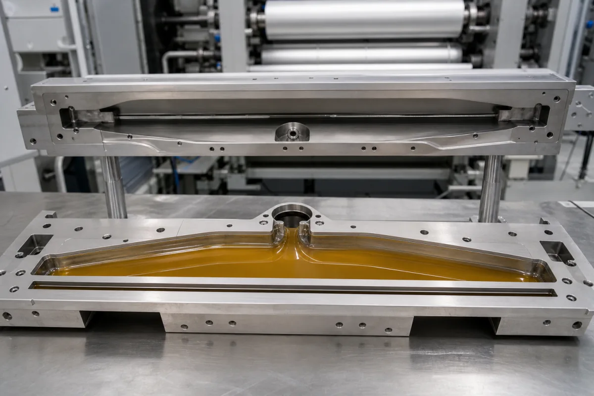
Manifold in a manufacturing environment
Representative product image. Confirm appearance and specifications with the manufacturer.

Product Specifications

Technical details and manufacturing context for Manifold

Definition
The manifold is a critical internal component of a slot-die coating head responsible for receiving coating fluid from the inlet and distributing it uniformly across the entire width of the die slot. It ensures consistent flow rates and pressure to achieve uniform coating thickness on the substrate. The manifold's internal geometry, often featuring a tapered or specially designed flow channel, gradually expands to distribute the fluid across the width. It maintains laminar flow and minimizes pressure variations to deliver a consistent fluid curtain through the die slot. This component is available in materials such as stainless steel 316L, aluminum alloy, and PTFE-coated steel, each selected based on the chemical compatibility and wear resistance required for the specific coating fluid. Key parameters include operating pressure (1.0–1.6 MPa), flow rate (0.5–5.0 L/min), temperature range (-10–80 °C), internal volume (0.5–2.0 L), surface roughness (Ra 0.2–0.4 µm, ISO 4287), material grade (316L, ASTM A240), weight (15–30 kg), die width (300–2000 mm), pressure drop (0.1–0.3 MPa), and leakage rate (0.01–0.05 mL/min). These values are reference ranges and must be verified for the specific model and application. The manifold is designed for use in slot-die coating systems, where uniform distribution is essential for coating quality. Proper selection requires consideration of the coating fluid's viscosity, temperature sensitivity, and required flow rate. Verification of the manifold's performance should include checks for pressure drop, flow uniformity, and leakage under rated conditions. Maintenance signals include increased pressure drop, uneven coating thickness, or visible wear on internal surfaces. Failure boundaries include operating outside the specified pressure or temperature ranges, which can lead to inadequate sealing or material degradation. Always consult the legal manufacturer or supplier to confirm model-specific values and standards.
Working Principle
Coating fluid enters the manifold through a central or side inlet. The internal geometry of the manifold (often with a tapered or specially designed flow channel) gradually expands to distribute the fluid across the width. It maintains laminar flow and minimizes pressure variations to deliver a consistent fluid curtain through the die slot.
Common Materials
Stainless steel 316L, Aluminum alloy, PTFE-coated steel
Technical Parameters
ParameterTypical rangeNotes & selection driver
Operating Pressure1.0–1.6 MPa
Flow Rate0.5–5.0 L/minUniform distribution across die width
Temperature Range-10–80 °CMaterial viscosity changes with temperature
Internal Volume0.5–2.0 LAffects residence time and purging efficiency
Surface RoughnessRa 0.2–0.4 µmSmooth finish prevents material buildupISO 4287
Material Grade316LCorrosion resistant for coating fluidsASTM A240
Weight15–30 kgDepends on die width and configuration
Die Width300–2000 mmDetermines coating width
Pressure Drop0.1–0.3 MPaEnsures uniform flow distribution
Leakage Rate0.01–0.05 mL/minZero leakage at rated pressure

Ranges are indicative industry figures for RFQ preparation, not a supplier commitment. Confirm every value and standard with the legal manufacturer before ordering.

Components / BOM
  • Inlet port Part
    Receives coating fluid from the pump system
    Material: Stainless steel
  • Distribution chamber
    Internal volume where fluid is distributed across width
    Material: Stainless steel or aluminum
  • Flow distribution channels Part
    Guides fluid evenly to the die slot
    Material: Machined metal with polished surfaces

Applied To / Applications

This component is essential for the following industrial systems and equipment:

Industrial Ecosystem & Supply Chain Structure

Complementary Systems
Downstream Applications
Specialized Tooling

Application Fit & Sizing Matrix

Operational Limits
pressure: Up to 100 bar (1500 psi) maximum operating pressure
flow rate: 0.1 to 100 L/min (depending on manifold size and design)
temperature: Typically -20°C to 200°C (dependent on seal materials)
slurry concentration: Up to 60% solids by weight (varies with particle size and viscosity)
Media Compatibility
✓ Aqueous polymer solutions ✓ Solvent-based coatings ✓ UV-curable resins
Unsuitable: Highly abrasive slurries with large particles (>100 μm)
Sizing Data Required
  • Coating width (mm)
  • Target wet film thickness (μm)
  • Coating material viscosity (cP)

Reliability & Engineering Risk Analysis

Failure Mode & Root Cause
Crevice corrosion
Cause: Stagnant fluid accumulation in low-flow areas or under gaskets, combined with corrosive media or chlorides, leading to localized pitting and material degradation.
Thermal fatigue cracking
Cause: Cyclic thermal stresses from repeated heating/cooling cycles or temperature fluctuations, particularly at welded joints or sharp transitions, causing crack initiation and propagation.
Maintenance Indicators
  • Visible weeping or small leaks at flange connections or welded seams, indicating seal degradation or crack formation.
  • Unusual vibration or audible hammering noises during operation, suggesting flow-induced resonance, water hammer, or internal component failure.
Engineering Tips
  • Implement regular ultrasonic thickness testing at high-risk areas (e.g., bends, welds, outlets) to monitor wall thinning and schedule predictive replacements before failure.
  • Design and maintain proper drainage slopes and avoid dead legs to prevent fluid stagnation, and consider corrosion inhibitors or material upgrades (e.g., duplex stainless steel) for aggressive service environments.

Indicative industry ranges for design and RFQ preparation. Confirm the exact figures and applicable standard with the manufacturer before specifying.

Compliance & Manufacturing Standards

Applicable Standards
ASME B16.5 - Pipe Flanges and Flanged Fittings PED 2014/68/EU - Pressure Equipment Directive (CE marking)

Quoted from the published standard.

Manufacturing Precision
  • Bore diameter: +/-0.05mm
  • Surface flatness: 0.1mm per 100mm
Quality Inspection
  • Hydrostatic Pressure Test
  • Dimensional Verification with CMM

Manufacturers of Manifold

Manufacturer profiles associated with Manifold.

Sourcing Manifold from China?
Tell us your specification and target quantity — we will match it against manufacturer records and come back with the factories that fit.
Request manufacturers We manufacture this

Manufacturer listings support early research and capability understanding. They are not certification, ranking, or transaction guarantees.

Share this page
Technical documentation
Request current drawings, revision history, and a signed specification sheet.
Manufacturing capability
Verify equipment lists, process limits, capacity, and representative production evidence.
Inspection readiness
Confirm test methods, calibrated equipment, sampling plans, and traceable reports.
Supplier transparency
Check the legal entity, factory address, ownership, certifications, and direct contacts.

CNFX does not score or rank suppliers. Buyers must verify all claims and documents with the legal manufacturer before ordering.

Supply Chain Compatible Machinery & Devices

Hydraulic Press

Industrial machine using hydraulic pressure to compress, form, or assemble materials

Explore Specs →
Heavy-Duty CNC Plasma Cutting Machine

The Heavy-Duty CNC Plasma Cutting Machine is a standalone industrial device designed for cutting conductive metals such as steel, stainless steel, aluminum, and copper alloys.

Explore Specs →
Automated Powder Coating System

Integrated industrial system for applying dry powder coatings to metal substrates.

Explore Specs →
Centrifugal Pump Impeller

The centrifugal pump impeller is a critical rotating component that converts mechanical energy from the motor into kinetic energy in fluid systems.

Explore Specs →

Frequently Asked Questions

What is the role of the manifold in a slot-die coating head?

The manifold receives coating fluid from the inlet and distributes it uniformly across the die width, ensuring consistent flow and pressure for uniform coating thickness.

What materials are available for the manifold?

The manifold can be made of stainless steel 316L, aluminum alloy, or PTFE-coated steel, depending on the chemical compatibility and wear resistance required.

What are the key parameters to verify for a manifold?

Key parameters include operating pressure (1.0–1.6 MPa), flow rate (0.5–5.0 L/min), temperature range (-10–80 °C), internal volume (0.5–2.0 L), surface roughness (Ra 0.2–0.4 µm), and leakage rate (0.01–0.05 mL/min). These are reference ranges and must be confirmed for the specific model.

How can I ensure the manifold performs correctly?

Verify that the operating conditions (pressure, temperature, flow) are within the specified ranges, and check for uniform coating thickness and no leakage. Regular maintenance includes inspecting internal surfaces for wear or buildup.

Data Basis

Editorial classification, named public sources where available, and source-reviewed manufacturer records.

Preliminary Technical Classification
This page supports structured research, RFQ preparation, and supplier evaluation. It does not replace buyer-led supplier qualification, standards review, or technical approval.
Buyer enquiry

Request manufacturing insight for Manifold

Ask for use case, specification boundaries, supplier type, and RFQ preparation information for this product.

Where it goes
Straight to the CNFX editorial desk, and to the manufacturer if this product is linked to a claimed profile. Nothing is broadcast to a supplier list.
Your details stay here
We do not sell or rent enquiry data, and we do not add you to a mailing list. Used only to answer this request.
No commission, no middleman
CNFX is a directory. We take no cut of any order and never negotiate on a supplier's behalf.
What we don't claim
A listing is not an endorsement. Qualify every supplier and verify every figure yourself before ordering.

Your business information is used only to process this request.

Thank you! Your message has been sent. We'll respond within 1–3 business days.
Sorry, we couldn't send your message. Please try again, or email us at [email protected].

Need to Manufacture Manifold?

Compare manufacturer profiles with relevant product and process capability.

Previous Product
Z-axis Ram/Spindle
Last Product
Get QuotesChat