Editorial Technical Reference

Outlet Nozzle/Port with Valve

This page explains how Outlet Nozzle/Port with Valve is classified within Machinery and Equipment Manufacturing. Technical values and manufacturer relationships are research references; confirm the current specification and supplier evidence for each order.

Technical Definition & Core Assembly

A component that controls the discharge of fluids from a collection tank through an integrated valve mechanism.
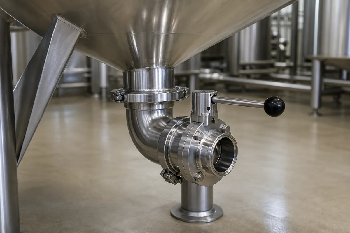
Outlet Nozzle/Port with Valve in a manufacturing environment
Representative product image. Confirm appearance and specifications with the manufacturer.

Product Specifications

Technical details and manufacturing context for Outlet Nozzle/Port with Valve

Definition
An outlet nozzle or port equipped with a valve, serving as the controlled discharge point for liquids or gases from a product collection tank. It regulates flow, prevents backflow, and allows for maintenance isolation while maintaining tank integrity. The valve mechanism (typically ball, gate, or butterfly type) opens or closes to control fluid flow through the nozzle/port. When open, fluid exits the tank through the nozzle; when closed, it seals the outlet to prevent leakage or allow system isolation. This component is commonly used in industrial tanks, pressure vessels, and process equipment where controlled discharge is required. It is available in nominal diameters from 15 to 50 mm (ISO 6708), with operating pressures from 1.0 to 1.6 MPa and operating temperatures from -20 to 80 °C. The flow coefficient (Cv) ranges from 2.5 to 15 US gal/min at full open, depending on size. Leakage rates meet Class VI, ranging from 0.01 to 0.1 mL/min. Seat material hardness is 80 to 95 Shore A (ISO 7619-1), and body material grades include 304 to 316 stainless steel (ASTM A276). Connections are threaded or weld-end, with BSP sizes from G1/2 to G2 (ISO 228-1). Overall length ranges from 80 to 200 mm, weight from 0.5 to 3.5 kg, actuation torque from 5 to 20 N·m, and cycle life from 10,000 to 50,000 cycles. These values are typical ranges for standard models; actual specifications must be confirmed with the manufacturer for the specific application. The component is designed for use in systems where reliable flow control and leak-tight sealing are critical. It is suitable for a variety of media, including corrosive fluids, when constructed from appropriate materials. Proper installation and maintenance are essential to ensure long service life and safe operation. Always verify model-specific parameters and compliance with relevant standards before procurement.
Working Principle
The valve mechanism (typically ball, gate, or butterfly type) opens or closes to control fluid flow through the nozzle/port. When open, fluid exits the tank through the nozzle; when closed, it seals the outlet to prevent leakage or allow system isolation. The valve is actuated manually or automatically, and the seat material provides a tight seal against leakage. The operating pressure and temperature ranges are limited by the seal material and valve design. The flow coefficient (Cv) indicates the flow capacity at full open, and the leakage rate Class VI. The component is designed to maintain tank integrity and allow for maintenance isolation.
Common Materials
Stainless Steel 316L
Technical Parameters
ParameterTypical rangeNotes & selection driver
Nominal Diameter15–50 mmCommon sizes for tank outletsISO 6708
Operating Temperature-20–80 °CSeal material limits range
Flow Coefficient (Cv)2.5–15 US gal/minAt full open, based on size
Leakage Rate0.01–0.1 mL/minClass VI seat leakageISO 5208
Seat Material Hardness80–95 Shore ASofter seat improves sealingISO 7619-1
Body Material Grade304–316 ASTM316 for corrosive mediaASTM A276
Connection TypeG1/2–G2 BSPThreaded or weld-endISO 228-1
Overall Length80–200 mmDepends on size and valve type
Weight0.5–3.5 kgIncreases with size and material
Actuation Torque5–20 N·mFor manual handle operation
Cycle Life10000–50000 cyclesDepends on seal and maintenance

Ranges are indicative industry figures for RFQ preparation, not a supplier commitment. Confirm every value and standard with the legal manufacturer before ordering.

Components / BOM
  • Valve Body
    Main housing containing the valve mechanism and providing structural integrity
    Material: Stainless Steel
  • Valve Actuator
    Mechanism to open and close the valve (manual lever, pneumatic, or electric)
    Material: Stainless Steel/Aluminum
  • Sealing Gasket Part
    Creates leak-proof seal between valve and tank connection
    Material: PTFE/FKM Rubber
  • Connection Flange Part
    Interface for mounting to the tank outlet
    Material: Stainless Steel
  • Outlet Nozzle
    The short spout through which fluid actually leaves the tank.
    Material: Stainless Steel
  • Valve Mechanism (Ball, Gate, or Butterfly)
    The moving closure element that opens or shuts the flow path.
    Material: Stainless Steel
  • Valve Seat
    The fixed face the closure element presses onto, which is what actually holds the shutoff tight.
    Material: PTFE / metal seat

Industry Taxonomies & Aliases

Commonly used trade names and technical identifiers for Outlet Nozzle/Port with Valve.

Applied To / Applications

This component is essential for the following industrial systems and equipment:

Industrial Ecosystem & Supply Chain Structure

Complementary Systems
Downstream Applications
Specialized Tooling

Application Fit & Sizing Matrix

Operational Limits
pressure: 0 to 10 bar (max operating pressure)
flow rate: Up to 50 m³/h (dependent on port size)
temperature: -20°C to +80°C
slurry concentration: Up to 30% solids by weight
Media Compatibility
✓ Water and aqueous solutions ✓ Petroleum-based fluids ✓ Chemical slurries with neutral pH
Unsuitable: Highly corrosive acids (e.g., concentrated sulfuric acid)
Sizing Data Required
  • Required flow rate (m³/h)
  • Operating pressure (bar)
  • Port connection size (DN/mm)

Reliability & Engineering Risk Analysis

Failure Mode & Root Cause
Cavitation damage
Cause: Rapid pressure drop across the valve creating vapor bubbles that implode against metal surfaces, causing pitting and material loss
Corrosion and erosion
Cause: Chemical attack from process fluids combined with high-velocity particle impingement, accelerated by improper material selection or operating outside design parameters
Maintenance Indicators
  • Unusual whistling or hissing sounds during operation indicating flow restriction or cavitation
  • Visible external leakage, weeping, or discoloration around valve body or nozzle connections
Engineering Tips
  • Install pressure gauges upstream and downstream to monitor pressure differentials and ensure operation within cavitation-free ranges
  • Implement routine ultrasonic thickness testing on nozzle walls and valve bodies to detect thinning before catastrophic failure occurs

Indicative industry ranges for design and RFQ preparation. Confirm the exact figures and applicable standard with the manufacturer before specifying.

Compliance & Manufacturing Standards

Applicable Standards
ISO 5208: Industrial valves - Pressure testing of valves ANSI/ASME B16.34: Valves - Flanged, Threaded, and Welding End DIN EN 12266-1: Industrial valves - Testing of metallic valves - Part 1: Pressure tests, test procedures and acceptance criteria

Quoted from the published standard.

Manufacturing Precision
  • Bore diameter: +/-0.025mm
  • Surface flatness at sealing interface: 0.05mm
Quality Inspection
  • Hydrostatic pressure test
  • Dye penetrant inspection for surface defects

Manufacturers of Outlet Nozzle/Port with Valve

Manufacturer profiles associated with Outlet Nozzle/Port with Valve.

Sourcing Outlet Nozzle/Port with Valve from China?
Tell us your specification and target quantity — we will match it against manufacturer records and come back with the factories that fit.
Request manufacturers We manufacture this

Manufacturer listings support early research and capability understanding. They are not certification, ranking, or transaction guarantees.

Share this page
Technical documentation
Request current drawings, revision history, and a signed specification sheet.
Manufacturing capability
Verify equipment lists, process limits, capacity, and representative production evidence.
Inspection readiness
Confirm test methods, calibrated equipment, sampling plans, and traceable reports.
Supplier transparency
Check the legal entity, factory address, ownership, certifications, and direct contacts.

CNFX does not score or rank suppliers. Buyers must verify all claims and documents with the legal manufacturer before ordering.

Supply Chain Compatible Machinery & Devices

Automated Powder Coating System

Integrated industrial system for applying dry powder coatings to metal substrates.

Explore Specs →
Centrifugal Pump Impeller

The centrifugal pump impeller is a critical rotating component that converts mechanical energy from the motor into kinetic energy in fluid systems.

Explore Specs →
High-Precision CNC Laser Cutting Machine

Computer-controlled industrial machine using focused laser beams to cut sheet metal with micron-level accuracy.

Explore Specs →
Industrial-Grade Hydraulic Cylinder Piston Rod

This industrial-grade piston rod is a precision-ground cylindrical component designed for use in hydraulic cylinders.

Explore Specs →

Frequently Asked Questions

What are the typical sizes and pressure ratings?

Typical nominal diameters range from 15 to 50 mm (ISO 6708), with operating pressures from 1.0 to 1.6 MPa. These are reference ranges; confirm the exact values for your model.

What materials are commonly used?

Body material grades include 304 to 316 stainless steel (ASTM A276). Seat material hardness is 80 to 95 Shore A (ISO 7619-1). Verify material compatibility with your media.

How does the valve prevent leakage?

The valve mechanism seals the outlet when closed, and the seat material provides a tight seal. Leakage rates meet Class VI, typically 0.01 to 0.1 mL/min. Ensure proper installation and maintenance.

What are the connection options?

Connections are threaded or weld-end, with BSP sizes from G1/2 to G2 (ISO 228-1). Choose the connection type based on your piping system and installation requirements.

Data Basis

Editorial classification, named public sources where available, and source-reviewed manufacturer records.

Preliminary Technical Classification
This page supports structured research, RFQ preparation, and supplier evaluation. It does not replace buyer-led supplier qualification, standards review, or technical approval.
Buyer enquiry

Request manufacturing insight for Outlet Nozzle/Port with Valve

Ask for use case, specification boundaries, supplier type, and RFQ preparation information for this product.

Where it goes
Straight to the CNFX editorial desk, and to the manufacturer if this product is linked to a claimed profile. Nothing is broadcast to a supplier list.
Your details stay here
We do not sell or rent enquiry data, and we do not add you to a mailing list. Used only to answer this request.
No commission, no middleman
CNFX is a directory. We take no cut of any order and never negotiate on a supplier's behalf.
What we don't claim
A listing is not an endorsement. Qualify every supplier and verify every figure yourself before ordering.

Your business information is used only to process this request.

Thank you! Your message has been sent. We'll respond within 1–3 business days.
Sorry, we couldn't send your message. Please try again, or email us at [email protected].

Need to Manufacture Outlet Nozzle/Port with Valve?

Compare manufacturer profiles with relevant product and process capability.

Previous Product
Z-axis Ram/Spindle
Last Product
Get QuotesChat