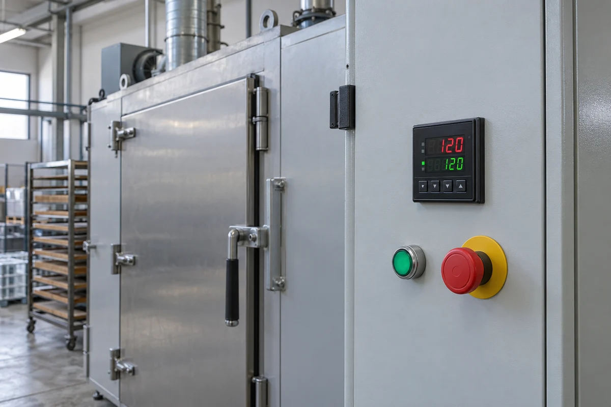
Follow the temperature signal from the sensor to the heater. Match the input, understand what the output can drive, and read accuracy together with its conditions.
CNFX editorial research · Sources checked October 12, 2026 · 10 sources
The controller closes a loop through the sensor and heater
The sensor measures the process and sends an electrical signal to the controller. The controller compares that process value (PV) with the setpoint (SP), computes a demand, and sends it to the selected output. An external SSR or power controller then regulates heater power when that output arrangement is used. The changing process temperature returns through the sensor to complete the loop. [8]
Proportional action responds to the present deviation. Integral action responds to the size and duration of the deviation, helping remove persistent offset. Derivative action responds to changes, including disturbances. The thermal response of the load still matters: a correct display reading and a fast input sampler alone do not establish how quickly an oven heats, overshoots or settles. [8]
02
Component structure: inside the controller and at the panel
This is a functional assembly reference using the E5CC documentation, not a manufacturing BOM or a list of interchangeable spares. Internal IC part numbers, PCB construction and material grades are not provided by the sources reviewed.
Component / function
Role in the assembled system
Documented scope
Input interface
Receives the selected thermocouple, resistance or analog signal for measurement.
The sensor is external; the input type and terminal connection must match it. Internal converter or PCB materials are not specified. [4]
Control processing
Compares the measured value with the setpoint and calculates the control demand.
A functional description of the control electronics; no particular microcontroller chip is identified. [8]
Output circuit
Provides the ordered relay contact, SSR drive signal or analog command.
Output configurations differ. An SSR drive circuit is not an integrated heater-power SSR or its heat sink. [4]
PV/SV display
Shows process and set values, with operating indicators.
The E5CC front drawing identifies two displays and indicators; the display assembly’s material grade is not stated. [10]
Front keys
Enter settings and navigate operating levels.
E5CC’s drawing identifies level, mode, shift/function, up and down keys. No membrane material or replacement-key compatibility is specified. [10]
Case, mounting adapter and front packing
Locate the controller in the panel and support the specified front seal.
E5CC/E5CC-B use Y92F-49 mounting adapter and Y92S-P8 packing. E5CC-U cannot be made waterproof by adding that packing. Housing alloy and gasket compound are not identified. [9]
Sensor probes, external SSRs/power controllers, current transformers and heater elements belong to the complete control loop. They are not automatically included with a panel controller. The reviewed E5CC accessory list identifies the CT and terminal cover as separately ordered items. [4][9]
03
Match the sensor before choosing the controller
The input card must accept your sensor and its range. Sensors themselves are defined by IEC standards, so name the standard type in the order.
Sensor
Defined by
What the controller must support
Watch for
Thermocouple
IEC 60584-1:2013 sets reference EMF functions and tolerances for types R, S, B, J, T, E, K, N, C and A, with the reference junction at 0 °C [1]
The exact letter type and range: Omron E5CC/E5CC-B lists K, J, T, E, L, U, N, R, S, B, C/W and PL II. The input setting also selects its temperature range. [4]
Types outside the IEC letter set, and extension cable of the wrong type
Pt100 resistance thermometer
IEC 60751:2022 (edition 3.0, January 2022) covers industrial platinum resistance thermometers and sensors [2]
Pt100 input; E5CC also supports JPt100, which uses a different resistance/temperature characteristic. Select the matching setting. [4][8]
The sensor's tolerance class, which adds to the controller's own error
Analog transmitter signal
Transmitter output, scaled in the controller
4–20 mA, 0–20 mA, 1–5 V, 0–5 V or 0–10 V on one published universal input [4]
Scaling range and who supplies loop power
A Chinese panel controller lists thermocouple types K, J, T, E, N, R, S and B plus Pt100, selected from the front panel [7]. Check the list against your sensor rather than assuming "universal input" covers it.
04
Controller accuracy is not system accuracy
The number on the datasheet covers the controller under stated conditions. The sensor and the cable add their own errors.
An accuracy figure without conditions cannot be compared
For Omron E5CC/E5CC-B at 23 °C ambient, the base thermocouple indication specification is ±(the greater of 0.3% of the reading or 1 °C), plus 1 digit. The Pt100 figure is ±(the greater of 0.2% of the reading or 0.8 °C), plus 1 digit. These are indication limits, not a guarantee of oven uniformity or process stability. E5CC-U has a different base thermocouple limit: the greater of 1% or 2 °C, plus 1 digit. Apply the sensor/range exceptions below before using any of these figures. [4]
Read the thermocouple footnote before calculating an error budget
The E5CC family table gives ±2 °C plus 1 digit for K on the −200 to 1,300 °C range, T/N at −100 °C or lower, and U/L throughout their ranges. It leaves type B accuracy unspecified at 400 °C or below, while also listing ±3 °C for 400–800 °C; the shared 400 °C boundary needs clarification. R/S at 200 °C or below use ±3 °C plus 1 digit. C/W and PL II use 0.3% of the reading with respective 3 °C and 2 °C minimum terms, plus 1 digit. A single headline percentage misses these exceptions. [4]
CN-TP1’s percentage needs a stated basis
Reewui advertises ±0.1% for CN-TP1 but does not define the reference quantity or ambient condition on this product page. Its numerical claim cannot yet be ranked against the conditional E5CC figures. Obtain the model’s indication specification, range and test conditions. [7]
The sensor's class adds its own tolerance
For Pt100 sensors, Class A is ±(0.15 + 0.002 |t|) °C and Class B is ±(0.3 + 0.005 |t|) °C [5]. At 100 °C that is about ±0.35 °C for Class A and ±0.8 °C for Class B, before any controller error. Specify the class you need on the sensor order.
The cable between sensor and controller matters
Thermocouple extension cable uses the same conductors as the thermocouple; compensating cable uses cheaper conductors that match only below a stated temperature at the connection point, for example below 100 °C for type KCB [6]. Name the cable type with the thermocouple type, and do not run plain copper wire to the controller.
05
Choose the output by what it switches
The control output drives your load or its power device. Ratings and life differ sharply between output types.
Sampling and switching are separate clocks. E5CC samples its input every 50 ms; its time-proportioning control period is selected from 0.1, 0.2, 0.5 s or whole seconds from 1 to 99. Sampling at 50 ms does not mean the relay should switch every 50 ms. For a simple illustration, a 40% demand over a 10 s period corresponds to 4 s on and 6 s off; this arithmetic illustrates duty ratio, not a recommended process setting. [4][8]
Relay output
E5CC/E5CC-B relay models provide an SPST-NO contact rated 250 VAC, 3 A for a resistive load, with a stated electrical life of 100,000 operations. E5CC-U uses SPDT instead. The rating is for the contact, not an assurance that any heater can connect directly; load and switching conditions affect service life. [4][10]
Voltage output for an SSR
The E5CC family’s PNP output supplies 12 VDC ±20% at up to 21 mA to an external SSR input. It does not supply heater power. CN-TP1 lists a 12 VDC pulse option. Match the SSR input voltage and current requirements before wiring. [4][7]
Current output
E5CC current-output models provide 4–20 mA or 0–20 mA into a load of at most 500 Ω; CN-TP1 offers a 4–20 mA option. This commands a compatible power controller or actuator. Select the exact output/alarm combination from the ordering code rather than assuming every option is fitted. [4][7]
06
Read the controller’s panel ratings separately from the process temperature
These are documented E5CC-family examples, not generic limits for PID controllers or CN-TP1 specifications. Input compatibility, accuracy and output selection are explained in the preceding sections.
Parameter
Published example / condition
What it changes
Temperature input range
Selected by thermocouple/RTD type and configured range. [4]
The process measuring range is separate from the cabinet ambient limit. Specify the sensor range and process limits together.
Supply / power budget
E5CC family: A code 100–240 VAC; D code 24 VAC or 24 VDC. Option 000: at most 5.2 VA on mains, 3.1 VA on 24 VAC, or 1.6 W on 24 VDC. Other options: 6.5 VA, 4.1 VA or 2.3 W respectively. [4]
Size the control supply for the ordered option. This consumption excludes the heater load.
Sampling / output resolution
50 ms input sampling; linear-current output resolution approximately 10,000 levels. [4]
Resolution counts discrete output levels; it does not measure indication accuracy. Relay and analog outputs require different descriptions.
Applies at the controller, not inside the heated process.
Storage / operating humidity
Storage −25 to 65 °C without condensation or icing; operating humidity 25–85%. [4]
Shipping/storage and powered operation have distinct conditions.
Ingress protection
E5CC/E5CC-B: front IP66/UL Type 1, rear case IP20, terminals IP00. E5CC-U front: IP50. [4]
Front protection is conditional on installation; the rear terminals need a suitable enclosure.
Face / opening / depth
E5CC face 48 × 48 mm; separate opening 45 (+0.6/−0) mm square. The drawing shows 60 mm body depth and 73.1 mm overall dimension. [9]
Allow space for terminals, covers and wiring; face dimensions are not the cutout.
Mass
E5CC/E5CC-B controller approximately 120 g, mounting adapter approximately 10 g; E5CC-U controller approximately 100 g. [4]
Use the mass for the selected controller and mounting arrangement when planning the panel assembly.
07
Seven steps to a complete specification
Work through these in order; each answer narrows the model code.
Sensor and range
Thermocouple letter type or Pt100 class, and the temperature range to display [1][2].
Control output and load
Relay, SSR drive or current output, sized to the heater or power device above.
Control mode
ON/OFF or PID with auto-tuning; one range offers 2-PID with 40 % and 100 % auto-tuning, self-tuning and heating/cooling control [4], another PID with auto-tuning, ON/OFF and manual/auto transfer [7].
Alarms
Count and type: deviation, absolute value and loop-break alarms on one model [7]; heater-burnout and SSR-failure alarms set from 0.1 to 49.9 A need a current transformer option on another [4].
Supply voltage
100–240 VAC or 24 VAC/DC on one range [4]. One Chinese page lists both 85–265 VAC and 100–240 VAC for the same model, so confirm the rating in writing [7].
Communication
For E5CC models with communications, RS-485 is two-wire, half-duplex; the current specification lists Modbus or CompoWay/F at 9,600, 19,200, 38,400 or 57,600 bps. CN-TP1 lists optional RS-485 Modbus RTU. Match protocol, speed and framing with the host. [4][7]
Panel size and cutout
E5CC has a 48 × 48 mm face, but a separately mounted unit needs a 45 (+0.6/−0) mm square opening; recommended panel thickness is 1–5 mm. Group mounting does not provide waterproofing. Reewui’s “Engineering drawings” image is a terminal diagram, not a dimensioned cutout drawing; request the latter for the selected CN-TP1 size. [9][7]
08
Service the panel connection and seal without opening the electronics
For the documented E5CC/E5EC, the manufacturer instructs users to isolate power for service, keep ventilation clear, separate signal wiring from high-current power wiring, and avoid opening or repairing the controller’s internals. Clean the controller with a soft dry cloth. Its relay life depends on load and switching conditions; persistent output trouble is a reason to inspect the circuit, not simply retune PID. These precautions come from the archived model sheet, whose revision is identified in Sources. [10]
Inspect the front packing when sealing matters. Omron says Y92S-P8 can deteriorate, shrink or harden; replacement timing depends on the environment, with three years offered only as a rough reference. Group-mounted controllers are not waterproof, and adding this packing does not waterproof E5CC-U. [9]
Controller alarms can fail with the controller. The E5CC/E5EC precautions call for appropriate independent monitoring where malfunction could cause damage. Treat the process protection circuit separately from normal temperature regulation. [10]
09
Safety and EMC documents to ask for
A controller sits in a powered panel; ask for documents that name the model you buy.
Safety: IEC 61010-1 consolidated edition 3.1 (January 2017) includes industrial process-control equipment. Omron lists applicable approvals and conformance for the E5CC family, with model conditions: for example, E5CC-U UL listing requires its specified P2CF-11 or P2CF-11-E socket, not P3GA-11. A family-level list is not a certificate for another model. [3][4]
EMC: Omron lists EN 61326-1 for the E5CC family in an industrial electromagnetic environment. Request the declaration or test evidence for the actual ordered model and destination. [4]
No model-specific safety or EMC evidence was identified on the CN-TP1 product page. This is a limit of this review, not proof that the manufacturer has no certificates. [7]
If your process requires traceable temperature records, order a calibration certificate for the controller and the sensor separately.
10
Copy this RFQ and fill in the brackets
Paste it into your enquiry below or into an email to a maker, then replace every bracket.
Product: panel PID temperature controller, [48×48 / 48×96 / 96×96] mm, quantity [units]
Sensor input: [thermocouple type K/J/T/N/R/S... or Pt100 Class A/B or 4–20 mA], range [min] to [max] °C
Control output 1: [relay / SSR drive 12 VDC / 4–20 mA], load: [heater kW, SSR model or power controller]
Control output 2: [none / cooling: relay or SSR drive]
Control mode: [PID with auto-tuning / ON-OFF]; heating/cooling: [yes/no]
Alarms: [number] x [deviation / absolute / loop break / heater burnout with CT]
Supply voltage: [100–240 VAC / 24 VAC/DC]
Communication: [none / RS-485 Modbus RTU]
Panel cutout: please send the dimensioned drawing; panel thickness [mm], rear wiring clearance [mm]
Installation: cabinet ambient [°C], humidity/condensation [conditions], required front/rear protection [rating]
Accuracy: state indication accuracy with its basis, ambient temperature and sensor/range exceptions
Documents: IEC/EN 61010-1 and EN 61326 evidence or test report for this model code; [calibration certificate if required]
Delivery to [country], target date [date]
3 companies list this product among what they make. Company figures are quoted from each
company's own website; every card states where the relationship came from.
ReeWui Automation Technology (Shanghai) Co., Ltd.
Shanghai, CN
Reewui lists CN-TP1 with thermocouple/Pt100 inputs, relay/SSR-drive/current output options and optional RS-485 Modbus RTU. Its supply-voltage conflict, undefined accuracy basis and missing dimensioned cutout are discussed above; do not infer a complete ordered configuration from the family page.
Product scope checked 2026-10-09
Managed by the manufacturer
Listed on the company's own website
Maxwell’s catalogue separates basic panel PID controllers from ramp-and-soak models such as PU90. It also lists KDF100 as an integrated temperature controller and SCR power regulator, which is a different package from an SSR-drive panel controller. Company-level CE labels do not establish conformity of the exact ordered model.
Product scope checked 2026-10-09
Founded 2011
CE
Listed on the company's own website · profile compiled by CNFX from public sources
Listed there as: “PID Temperature Controller” View source page ↗maxwell-fa.com · recorded 2026-08-22
Strong Electric lists TC4 panel PID controllers with thermocouple/RTD inputs and relay, SSR-drive or 4–20 mA output options, plus optional communications. Its catalogue also includes manual heating-power controllers that do not measure temperature; those are a different product from a closed-loop PID controller.
Product scope checked 2026-10-09
Listed on the company's own website · profile compiled by CNFX from public sources
Listed there as: “TC4 Series PID Temperature Controller” View source page ↗strong-ele.com · recorded 2026-09-12
Explore company information and manufacturing capabilities, then discuss the scope of your project with a relevant supplier.
Share this page
Compiled and source-reviewed by the CNFX editorial team.
Each manufacturer above links to the page on that company's own website where the product is listed, with the date we checked it. How we source and review
· Page last updated 13 October 2026
Buyer questions
Is a ±0.1 % controller more accurate than one rated ±0.3 %?
A percentage needs a reference quantity, a temperature range and test conditions. E5CC/E5CC-B’s base thermocouple indication figure at 23 °C is the greater of ±0.3% of the reading or ±1 °C, plus 1 digit, with sensor/range exceptions. CN-TP1’s ±0.1% headline does not provide the same conditions, so it cannot be ranked directly. [4][7]
Can one controller take both thermocouples and Pt100 sensors?
Panel controllers with a universal input exist; one range accepts twelve thermocouple types plus Pt100 and JPt100, and a Chinese model lists eight thermocouple types plus Pt100. The input type and range are set in the controller. [4][7]
Relay or SSR output for a heater?
A relay contact on one published range is rated 250 VAC, 3 A resistive with an electrical life of 100,000 operations, which a short control period can use up quickly. An SSR drive output switches a solid-state relay instead of a contact. [4]
Why does my controller read differently from a reference thermometer?
Sensor tolerance, the selected input characteristic and the cable connection all matter. At 100 °C the published Pt100 Class B formula gives ±0.8 °C before controller error. Thermocouple extension or compensating cable must match the thermocouple and its permitted connection temperature; the error depends on the actual junction temperatures. [5][6]
Which standard should a Pt100 sensor be ordered to?
IEC 60751; the current edition is 3.0, published in January 2022. State the tolerance class as well. [2]
Sources and what still needs a direct check
Sources checked 2026-10-12. Public IEC abstracts define standard scope. Named-model ratings use current Omron web specifications and drawings; the archived PDF is separately identified for front-panel nomenclature and service precautions. New checks in this repair were made on 9 October 2026. These sources do not certify suppliers.
CN-TP1 supply claims conflict (85–265 VAC in the summary versus 100–240 VAC in its table/order code). Its ±0.1% indication basis and dimensioned cutout remain to be supplied.
No model-specific Chinese manufacturer safety/EMC evidence was verified in the reviewed product page. Request documents for the ordered configuration.
IEC full texts were not read; standard references rely on official public abstracts. E5CC data illustrates named models, not every PID controller.
Omron’s catalogue lists a newer H177-E1-19 PDF, but its download could not be read in this review. Current official web specifications/drawings are used for ratings; the older PDF is identified separately for nomenclature and precautions.
Buyer enquiry
Request manufacturing insight
for PID Temperature Controller
Ask for use case, specification boundaries, supplier type, and RFQ preparation
information for this product.
Where it goes
Straight to the CNFX editorial desk, and to the manufacturer if this product is
linked to a claimed profile. Nothing is broadcast to a supplier list.
Your details stay here
We do not sell or rent enquiry data, and we do not add you to a mailing list.
Used only to answer this request.
No commission, no middleman
CNFX is a directory. We take no cut of any order and never negotiate on a
supplier's behalf.
What to include
Share your product specifications, quantity, destination and target delivery date.
Need to Manufacture PID Temperature Controller?
Compare manufacturer profiles with relevant product and process capability.