Editorial Technical Reference

Position Encoder/Resolver

This page explains how Position Encoder/Resolver is classified within Machinery and Equipment Manufacturing. Technical values and manufacturer relationships are research references; confirm the current specification and supplier evidence for each order.

Technical Definition & Core Assembly

A sensor that detects and converts the angular or linear position of a rotating or moving component into an electrical signal.
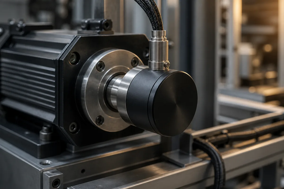
Representative product image. Confirm appearance and specifications with the manufacturer.

Product Specifications

Technical details and manufacturing context for Position Encoder/Resolver

Definition
A position encoder/resolver is a feedback component used in drive motors and actuators to measure the rotational angle or linear displacement of a shaft or mechanism. It provides real-time positional data to the control system, enabling closed-loop control for accurate speed regulation, torque control, and precise positioning in automated machinery and motion control systems. The device operates by generating an electrical signal—analog sine/cosine waves for resolvers, digital pulses for encoders—whose phase, frequency, or pulse count corresponds directly to the shaft's angular position. The control system interprets this signal to determine exact position, speed, and direction. Typical specifications include resolution of 10–16 bits, accuracy of ±0.01°, supply voltage of 5 V DC ±5% or 24 V DC ±10%, and output signals such as incremental (TTL/HTL) or absolute (SSI/BiSS). Operating temperature ranges from -40 to +85 °C, with protection class IP54–IP67 per IEC 60529. Shaft diameters are 6–14 mm, maximum rotational speed is 6000–12000 rpm, and moment of inertia is ≤ 5×10⁻⁶ kg·m². Housing is typically aluminum alloy, with stainless steel shaft. Weight ranges from 0.2–0.5 kg, and connection is via cable or M12 connector. These values are reference ranges; verify model-specific data with the manufacturer. The device is constructed with materials such as aluminum alloy, stainless steel, PCB, and magnetic or optical sensing elements. It is essential for applications requiring high dynamic response and reliability. Always confirm that the selected model meets the required resolution, accuracy, and environmental conditions for your specific application.
Working Principle
The encoder or resolver generates an electrical signal that varies with the angular position of the shaft. For resolvers, the output is analog sine and cosine waves whose amplitudes encode the angle. For encoders, the output is digital pulses (incremental) or a serial data stream (absolute) that represents position. The control system measures the phase, frequency, or pulse count to determine the exact position, speed, and direction of rotation. This feedback is used in closed-loop control to adjust motor operation for precise positioning and speed regulation.
Common Materials
Aluminum Alloy, Stainless Steel, PCB (Printed Circuit Board), Magnetic/Optical Sensing Elements
Technical Parameters
ParameterTypical rangeNotes & selection driver
Resolution10–16 bitHigher resolution for precise positioning
Accuracy±0.01 °Critical for closed-loop control
Supply Voltage5 V DC ±5% or 24 V DC ±10% V DCMatch with control system
Output SignalIncremental (TTL/HTL) or Absolute (SSI/BiSS)Choose based on controller interface
Operating Temperature-40–+85 °CExtended range for harsh environmentsIEC 60068-2-1/2
Protection ClassIP54–IP67Higher IP for dust/moistureIEC 60529
Shaft Diameter6–14 mmMatch with mating shaft
Max. Rotational Speed6000–12000 rpmExceeding may cause mechanical failure
Moment of Inertia≤ 5×10⁻⁶ kg·m²Low inertia for dynamic response
MaterialAluminum housing, stainless steel shaftCorrosion resistance
Weight0.2–0.5 kgConsider for mounting
Connection TypeCable or M12 connectorCable for fixed, connector for quick disconnect

Ranges are indicative industry figures for RFQ preparation, not a supplier commitment. Confirm every value and standard with the legal manufacturer before ordering.

Components / BOM
  • Rotor
    Rotates with the motor shaft, containing the pattern (optical disk, magnetic poles) that generates the position signal.
    Material: Aluminum/Steel with optical or magnetic coating
  • Stator/Sensor Head
    Stationary part containing light sources (LEDs), photodetectors, or magnetic sensors that read the rotor's pattern to generate electrical signals.
    Material: PCB with electronic components, housed in aluminum
  • Shaft Coupling
    Mechanically connects the encoder rotor to the motor shaft, ensuring accurate torque transmission and alignment.
    Material: Stainless Steel or Aluminum

Applied To / Applications

This component is essential for the following industrial systems and equipment:

Industrial Ecosystem & Supply Chain Structure

Complementary Systems
Downstream Applications
Specialized Tooling

Application Fit & Sizing Matrix

Operational Limits
pressure: Atmospheric to 2 bar (typical), IP67/IP69K rated for environmental protection
other spec: Resolution: 12-24 bit, Accuracy: ±0.1° to ±0.01°, Vibration: 10-2000 Hz at 10g, Shock: 100g for 6ms
temperature: -40°C to +125°C (operating), -55°C to +150°C (storage)
Media Compatibility
✓ Industrial machinery shafts ✓ Robotic arm joints ✓ CNC machine slides
Unsuitable: High-pressure hydraulic fluid immersion without proper sealing
Sizing Data Required
  • Required resolution/accuracy (bits/arc-seconds)
  • Mounting configuration (shaft/hollow/bearingless)
  • Electrical interface/output type (analog/digital/protocol)

Reliability & Engineering Risk Analysis

Failure Mode & Root Cause
Signal degradation or loss
Cause: Contamination ingress (dust, oil, moisture) compromising optical or magnetic elements, or electrical connector corrosion/loosening
Mechanical wear or misalignment
Cause: Bearing failure in rotary encoders, shaft coupling wear, or mounting misalignment causing excessive vibration/load
Maintenance Indicators
  • Intermittent or erratic position readings (e.g., machine 'hunting' or position jumps)
  • Unusual audible noise (grinding, clicking) from the encoder/resolver housing during rotation
Engineering Tips
  • Ensure proper IP-rated sealing and environmental protection (clean, dry, vibration-damped mounting) with regular connector inspection/cleaning
  • Implement precision alignment during installation, use flexible couplings to absorb misalignment, and monitor vibration trends for early bearing wear detection

Indicative industry ranges for design and RFQ preparation. Confirm the exact figures and applicable standard with the manufacturer before specifying.

Compliance & Manufacturing Standards

Applicable Standards
ISO 13849-1:2015 - Safety of machinery IEC 60034-1:2022 - Rotating electrical machines EN 61800-5-1:2007 - Adjustable speed electrical power drive systems

Quoted from the published standard.

Manufacturing Precision
  • Radial runout: ≤0.01mm
  • Shaft concentricity: ≤0.005mm
Quality Inspection
  • High-potential (hipot) insulation test
  • Signal accuracy verification test

Manufacturers of Position Encoder/Resolver

Manufacturer profiles associated with Position Encoder/Resolver.

Sourcing Position Encoder/Resolver from China?
Tell us your specification and target quantity — we will match it against manufacturer records and come back with the factories that fit.
Request manufacturers We manufacture this

Manufacturer listings support early research and capability understanding. They are not certification, ranking, or transaction guarantees.

Technical documentation
Request current drawings, revision history, and a signed specification sheet.
Manufacturing capability
Verify equipment lists, process limits, capacity, and representative production evidence.
Inspection readiness
Confirm test methods, calibrated equipment, sampling plans, and traceable reports.
Supplier transparency
Check the legal entity, factory address, ownership, certifications, and direct contacts.

CNFX does not score or rank suppliers. Buyers must verify all claims and documents with the legal manufacturer before ordering.

Supply Chain Compatible Machinery & Devices

Heavy-Duty CNC Plasma Cutting Machine

The Heavy-Duty CNC Plasma Cutting Machine is a standalone industrial device designed for cutting conductive metals such as steel, stainless steel, aluminum, and copper alloys.

Explore Specs →
Automated Powder Coating System

Integrated industrial system for applying dry powder coatings to metal substrates.

Explore Specs →
Centrifugal Pump Impeller

The centrifugal pump impeller is a critical rotating component that converts mechanical energy from the motor into kinetic energy in fluid systems.

Explore Specs →
High-Precision CNC Laser Cutting Machine

Computer-controlled industrial machine using focused laser beams to cut sheet metal with micron-level accuracy.

Explore Specs →

Frequently Asked Questions

What is the difference between an encoder and a resolver?

An encoder typically provides digital output signals (incremental or absolute) using optical or magnetic sensing, while a resolver provides analog sine/cosine signals. Encoders offer higher resolution in bits, while resolvers are often more robust in harsh environments.

How do I choose between incremental and absolute output?

Incremental encoders provide relative position and require a reference point at startup, while absolute encoders provide absolute position immediately. Choose based on your controller interface and whether you need position retention after power loss.

What is the significance of protection class IP54–IP67?

The IP rating indicates resistance to dust and water ingress. IP54 offers limited protection against dust and splashing water, while IP67 provides full dust protection and temporary immersion. Select based on your operating environment.

Can I use this encoder/resolver in high-speed applications?

The maximum rotational speed is 6000–12000 rpm, but the actual limit depends on the specific model and mechanical design. Exceeding the rated speed may cause mechanical failure. Verify the speed rating with the manufacturer for your application.

Data Basis

Editorial classification, named public sources where available, and source-reviewed manufacturer records.

Preliminary Technical Classification
This page supports structured research, RFQ preparation, and supplier evaluation. It does not replace buyer-led supplier qualification, standards review, or technical approval.
Buyer enquiry

Request manufacturing insight for Position Encoder/Resolver

Ask for use case, specification boundaries, supplier type, and RFQ preparation information for this product.

Where it goes
Straight to the CNFX editorial desk, and to the manufacturer if this product is linked to a claimed profile. Nothing is broadcast to a supplier list.
Your details stay here
We do not sell or rent enquiry data, and we do not add you to a mailing list. Used only to answer this request.
No commission, no middleman
CNFX is a directory. We take no cut of any order and never negotiate on a supplier's behalf.
What we don't claim
A listing is not an endorsement. Qualify every supplier and verify every figure yourself before ordering.

Your business information is used only to process this request.

Thank you! Your message has been sent. We'll respond within 1–3 business days.
Sorry, we couldn't send your message. Please try again, or email us at contact@cnfx.com.

Need to Manufacture Position Encoder/Resolver?

Compare manufacturer profiles with relevant product and process capability.

Previous Product
Position Encoder
Next Product
Position Encoders
Get QuotesChat