A tight headline tolerance does not tell you whether the mounting face, bore and thread will fit together. Start with the drawing revision and the features that matter to the assembly, then agree how the finished part will be measured.
This guide covers custom machined parts, not a standard machine or interchangeable assembly. Protolabs figures describe its published service guide; VMT figures are statements on its 6061 aluminium page. Neither defines a tolerance for every Chinese machining supplier.
CNFX editorial research · Sources checked October 12, 2026 · 5 sources
VMT publishes more than one tolerance figure on one 6061 aluminium page, including ±0.01 mm and ±0.005 mm. They do not identify one default for every feature. Compare them with an explicitly described service, then ask for a drawing-specific commitment [1][2].
Keep the arithmetic on one unit basis
The guide’s 1.000 in bracket at ±0.005 in has limits 0.995–1.005 in, exactly 25.273–25.527 mm. If a drawing instead states 25.4 ±0.13 mm, its arithmetic limits are 25.270–25.530 mm. These are two different specifications; a rounded conversion must not silently replace the original limit [2].
A tighter advertisement is not your accepted feature
VMT’s page supplies no basis for assigning its tightest figure to every drawing dimension. Ask the supplier to mark accepted tolerances and any exceptions on the controlled drawing, with the material condition and final processing state [1].
Claim or service
Published wording / conversion
What it leaves to resolve
VMT tolerance statements
Specification range ±0.001–±0.05 mm; separate text claims ±0.01 mm and up to ±0.005 mm [1]
No identified universal default or feature-specific validation in the cited statements.
Protolabs guide: standard
±0.005 in; exact conversion ±0.127 mm (guide rounds to ±0.13 mm) [2]
This is the named service’s published tolerance, not an industry standard.
Protolabs guide: precision
±0.002 in = ±0.0508 mm; guide rounds to ±0.051 mm [2]
Exceptional requirements must be identified when quoting.
Reamed holes and feature location
Reamed holes ±0.0005 in = ±0.0127 mm; feature locations ±0.002 in when machined on the same side [2]
Reaming and same-side location are stated conditions, not a promise for all bores and setups.
Finish wording
VMT lists Ra 0.1–3.2 and separately Ra 0.8, without a unit beside those figures [1]
Protolabs guide lists 63 µin on flat/perpendicular surfaces and 125 µin or better on curved surfaces. Agree the parameter, unit and measurement conditions [2].
02
Use GD&T where size tolerance is not enough
Specify the governing drawing standard and edition before interpreting a symbol. ASME lists Y14.5-2018 (R2024) as the version reaffirmed in 2024; that catalogue entry does not provide the complete standard text [3].
Position and datums
Identify the relevant reference features and the position control on the drawing. Datum setup is part of the agreed measurement plan, not merely a CMM report heading [4].
Flatness and cylindricity
Define the actual form requirement, separately from the reported nominal size. Do not adopt the older guide’s oblong-hole illustration as a universal statement that any diameter within two limits must conform [2][4].
Coaxial features
Mitutoyo’s 2019 explanation identifies removal of concentricity and symmetry in ASME Y14.5-2018 and discusses position/runout for coaxial features. Existing drawings governed by older editions need their own interpretation; do not substitute a control without design approval [4].
Size and form
Mitutoyo explains that ASME and ISO size/form conventions differ. Its presentation is technical education, not a replacement for the governing drawing standard or a feature-specific acceptance decision [4].
Protolabs’ guide requires a 3D model plus a 2D drawing for its GD&T service and describes human quotation review. Its undated guide’s 5–10 day lead time is a service statement, not a present quotation or a promise from the suppliers below [2].
03
Read the machined features as part of one drawing
Mounting faces, bores, threads and seal interfaces are features of a part. They are not necessarily separate purchased components. The table is a functional structure reference; a manufacturing BOM, quantities, inserts and material allocations require the actual part or assembly drawing. Machining removes material from stock to produce the specified geometry [2].
Feature
Role in the assembly
Drawing and material information needed
Mounting surface
Provides the contact/reference region used to attach or locate the part.
Identify the mating face, datum and flatness/finish requirement. Do not infer a material or coating from its name.
Bore / hole features
Provide openings for the intended fastener, shaft or passage; the drawing decides which.
State diameter, depth, location and required fit/form. A plain bore and a reamed hole are different quoted operations [2].
Threaded features
Provide the specified screw connection or adjustment interface.
State thread designation, class, usable depth and whether an insert is included. Tool reach and opposing-side threading require review [2].
Sealing surface, where present
Provides the drawn interface for the selected seal or gasket.
Provide the seal drawing and mating requirements: seal type, finish, leak performance and any treatment.
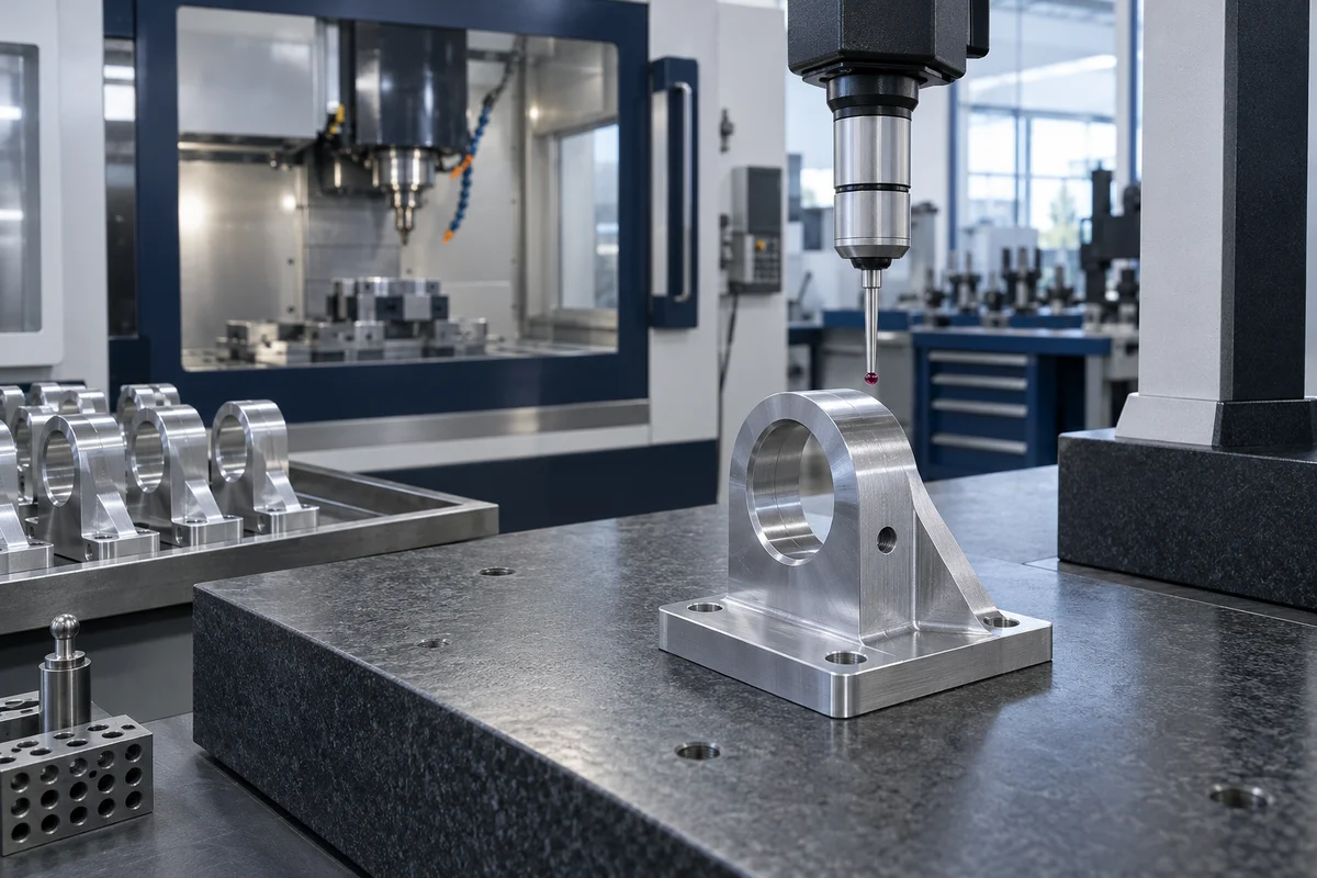
VMT lists 6061 and 6061-T6 machining. That supports its advertised material scope, not the alloy/temper of an unidentified part. The displayed scene is production context and supplies no manufacturing dimensions or evidence of a passed measurement [1].
04
Design features the machine can hold
Review accessibility and distortion with the proposed shop. The following numeric examples belong to Protolabs’ published process guidance, not to every machine or material [2].
The guide warns that walls 0.020 in (0.508 mm) or thinner can break during cutting or flex afterwards; its stated maximum wall height is 2 in (50.8 mm, rounded to 51 mm). Geometry, material and tooling still matter [2].
It gives 1–3° taper as a possible machining aid, not a mandatory draft for all machined parts. Its width-to-height 3:1 rule of thumb is not adopted here as a drawing acceptance criterion [2].
Small pockets and internal corners can require smaller cutters and extra tool changes. Agree a reachable corner geometry instead of assuming a sharp internal corner can be milled by any chosen cutter [2].
For recessed milled text, the guide specifies character spacing and cutting stroke of at least 0.020 in (about 0.5 mm). Its turned-text advice differs; marking must follow the selected process [2].
Confirm the usable threaded length. The guide warns that threading from opposite ends of a deep hole can cause mismatched or intersecting threads; a modelled through-hole does not establish uninterrupted full-depth threading [2].
VMT accepts 2D/3D drawing formats and offers DFM. Record whether an approved change affects the drawing revision, feature geometry or inspection requirement [1].
05
Specify dimensions, material and finish for the actual part
Use these fields to define the ordered part. Each requirement must follow a controlled drawing and the accepted quotation.
Field
Unit / basis
Meaning and evidence to supply
Dimensional tolerance
mm or in, explicitly stated
Give nominal dimensions and limits by feature; identify general and exceptional tolerances. Do not assign VMT’s tightest range to every dimension [1].
Surface roughness
Named parameter and unit
63 µin × 0.0254 = 1.6002 µm; 125 µin = 3.175 µm. This is unit arithmetic, not conversion between Ra and another parameter. Specify the actual surface and measurement conditions [2][4].
Geometric tolerance
Drawing standard, edition, zone and datums
Provide the complete callout and required relationships. A list of geometric tolerance numbers alone cannot define acceptance [4].
Material hardness
Specified scale and finished condition
If required by the design, state the hardness specification and test location/condition. Hardness depends on the specified material and processing condition.
Material grade
Exact grade, temper / heat treatment and stock specification
6061 and 6061-T6 appear in VMT’s scope. Identify the ordered condition and certificate; do not approve substitute alloys from a marketing equivalence list [1].
Part weight
kg or drawing mass
Provide mass or the controlled geometry and material needed to determine it. An acceptable mass depends on this part’s design, rather than a category-wide range.
Surface treatment
Process, thickness, masking and final dimensions
Identify anodizing/plating/other treatment where required. Protolabs discusses coating effects on close-fit dimensions; specify whether acceptance is before or after final treatment [2].
Supplier quality system
Certificate identity, validity and applicable site/scope
Ask for evidence appropriate to the contract. A quality-system claim is not a dimensional report or proof of medical suitability; the listed suppliers’ certificates have not been independently verified here.
ISO’s catalogue identifies ISO 1302:2002 as withdrawn and ISO 21920-1:2021 as its published successor for graphical surface-texture indication. Existing drawings must retain their governing references until the design owner authorises a revision. The public abstract does not supply the complete inspection procedure [5].
06
Ask for inspection documents up front
Agree the evidence before production, including which features are measured and in what final condition. A CMM name or “100% inspection” statement alone leaves the measurement method and reporting coverage open [4].
Drawing-linked report
Request results tied to drawing number/revision, measured features and acceptance limits. Agree datum setup, sampling/scan strategy and handling of measurement uncertainty; Mitutoyo explains that instruments and analysis methods affect results [4].
Material and lot traceability
Protolabs lists material certificates and heat-lot numbers among requested documentation. Ask which records accompany this order and whether finishing subcontractors are included [2].
FAI / PPAP / CoC
The guide offers first-article inspections, PPAP and certificates of conformance on request. They are documentation options, not automatically included or equivalent deliverables [2].
VMT inspection and scheduling claims
The page advertises 12 inspection stages, in-process checks every two hours and 100% dimensional inspection. It also lists samples at 7–10 days, standard 7–15 days, urgent 24-hour examples and batch delivery at 2–4 weeks. Specify the order’s coverage and schedule; these are not one unconditional commitment [1].
Handling and care of delivered parts
VMT describes protective packaging and separation against scratches. Agree protection of critical faces, thread/bore cleanliness and finish-compatible handling. Operating lubrication, cleaners and replacement intervals depend on the assembled product; none are established for this whole category [1].
07
Describe the drawing, finished condition and inspection evidence
Paste it into your enquiry below or into an email to a maker, then replace every bracket.
Part: [number / revision]; 2D drawing [file]; 3D model [file / revision]
Quantity: [prototype / batch / annual]; no design substitution without [approval]
Material: [grade / temper / stock specification]; traceability [heat / lot]
General dimensions: [drawing standard / edition / units / limits]
Critical features: [face / bore / thread / seal surface]; accepted exceptions [ ]
GD&T: [callouts / datums / governing standard and edition]
Threads: [designation / class / usable depth / insert and installation scope]
Finish: [parameter / units / surfaces / measurement conditions]
Treatment: [process / thickness / masking]; measure [before / after final finish]
Inspection: [FAI / feature report / CMM plan / sampling / CoC / material records]
Handling: [face protection / cleanliness / packaging / identification]
Delivery: [sample approval date / batch date / destination / incoterm]
The companies below cover general CNC parts, turned components and specialist mould/tooling work. Compare the actual process and material scope; certificates, headline tolerances and application marketing have not been independently verified as guarantees for your drawing.
Shenzhen VMT Metal Product Co., Limited
Guangming, Shenzhen, China (order production site to be verified), CN
VMT publishes custom 6061 aluminium milling, turning and combined-process work. Its product page gives tolerance and delivery figures; the factory page is marked updated March 2021 and names partner companies for stamping/die-casting. The product footer and factory page give different Guangming addresses. Confirm the actual production/finishing site, accepted drawing and inspection coverage per order.
Junyu lists CNC milling/turning, wire and die-sinking EDM, optical profile grinding, moulds and finished metal/plastic parts. Its ±0.002 mm grinding and ±0.005 mm EDM claims concern different processes; they are not a uniform CNC part tolerance. Published ISO/TS/IATF history is not a current certificate verification.
Anebon’s current service page lists CNC milling, turning, EDM, wire cutting and grinding for metal/plastic parts. It combines a down-to tolerance headline with feature-specific figures and ISO 2768 classes. Agree which rule and measurement plan governs the drawing rather than treating the headline as every feature’s limit.
Winhoo’s catalogue includes motor/pump, medical, aerospace and fixture machining in various metals. Those are component/application listings, not evidence it manufactures the complete motors or medical devices. Its contact page on the catalogue gives a Hong Kong address; the actual order-production site needs confirmation.
Langdi’s current category lists stamping-die components, carbide punches/inserts, profile grinding and wire-EDM parts. It is a specialist tooling scope rather than proof of the same general aluminium-part process.
The current LC Manufacturing page identifies Dongguan Licun Technology and lists medical-device components, stainless finishing and turn-mill work. It uses ISO 13485-aligned/completed wording and medical suitability claims without independent certificate or finished-device validation here. Confirm the contracting identity, process evidence and intended-use requirements.
OMET’s current catalogue lists mould cores/inserts, ejector and punch pins, connector tooling, grinding and CNC lathe/milling work. Its Hong Kong contact address does not establish the machining plant location. Request the particular material, tooling process and drawing-specific inspection rather than applying a minimum-tolerance headline to all parts.
PFTWORLD currently separates customised precision mechanical parts from sensors and linear-actuator products. Its homepage establishes a machining category; drawing-specific tolerances, certificates and inspection results require the actual quotation and supporting records. Request the concrete part offer and manufacturing route.
Dajin publishes custom turning/milling, shafts, pins, fasteners and other machined components, with centreless-grinding claims. The outside-diameter grinding figure is not a tolerance for every turned or milled feature. Material, size, geometry and accepted dimensions remain order-specific; certification claims are not independently checked here.
TONGCRX lists custom CNC parts, jigs/fixtures, tooling and prototype/low-volume work for optical, medical and other industries. Its headline certificate wording differs from the later ISO 13485-compliant wording. A listed CMM and ±0.005 mm claim do not establish certificate validity or acceptance of all features on a buyer’s drawing.
Explore company information and manufacturing capabilities, then discuss the scope of your project with a relevant supplier.
Share this page
Compiled and source-reviewed by the CNFX editorial team.
Each manufacturer above links to the page on that company's own website where the product is listed, with the date we checked it. How we source and review
· Page last updated 13 October 2026
Buyer questions
Does VMT’s ±0.001 mm statement apply to every feature?
Its page lists a tolerance range and separate ±0.01 mm and ±0.005 mm claims without identifying one feature-wide default. Obtain accepted drawing tolerances and any exceptions for the ordered material and geometry. [1]
Why do ±0.13 mm and the guide’s converted bracket limits differ?
±0.005 in converts exactly to ±0.127 mm. Around 25.4 mm that gives 25.273–25.527 mm. A drawing specifying ±0.13 mm instead gives 25.270–25.530 mm; use one unit basis consistently. [2]
Should I add concentricity under ASME Y14.5-2018?
Mitutoyo identifies removal of that control in the 2018 edition. The current ASME catalogue lists 2018 (R2024). Have the design owner choose the control for the actual function; older drawings need their specified edition interpreted. [4][3]
Is 63 µin the same as a guaranteed Ra 1.6 µm finish?
63 µin converts to 1.6002 µm, but unit arithmetic does not establish the parameter, filtering, measurement location or this supplier’s accepted finish. Identify those conditions on the drawing and quotation. [2][4]
Are the four displayed features a manufacturing BOM?
They are a drawing-oriented functional structure reference. A mounting face, bore, thread and optional seal face can belong to one part; manufacturing quantities, inserts and material allocations require the actual controlled drawing. [2]
Sources and what still needs a direct check
Sources checked 2026-10-12. Standards bodies and regulations define the requirements; manufacturer pages show published ranges for those models only. CNFX does not certify products or suppliers.