Editorial Technical Reference

Pressure Vessels

This page explains how Pressure Vessels is classified within Machinery and Equipment Manufacturing. Technical values and manufacturer relationships are research references; confirm the current specification and supplier evidence for each order.

Technical Definition & Core Assembly

A sealed container designed to hold fluids at a pressure substantially different from the ambient pressure, serving as the core housing for reverse osmosis membrane elements.
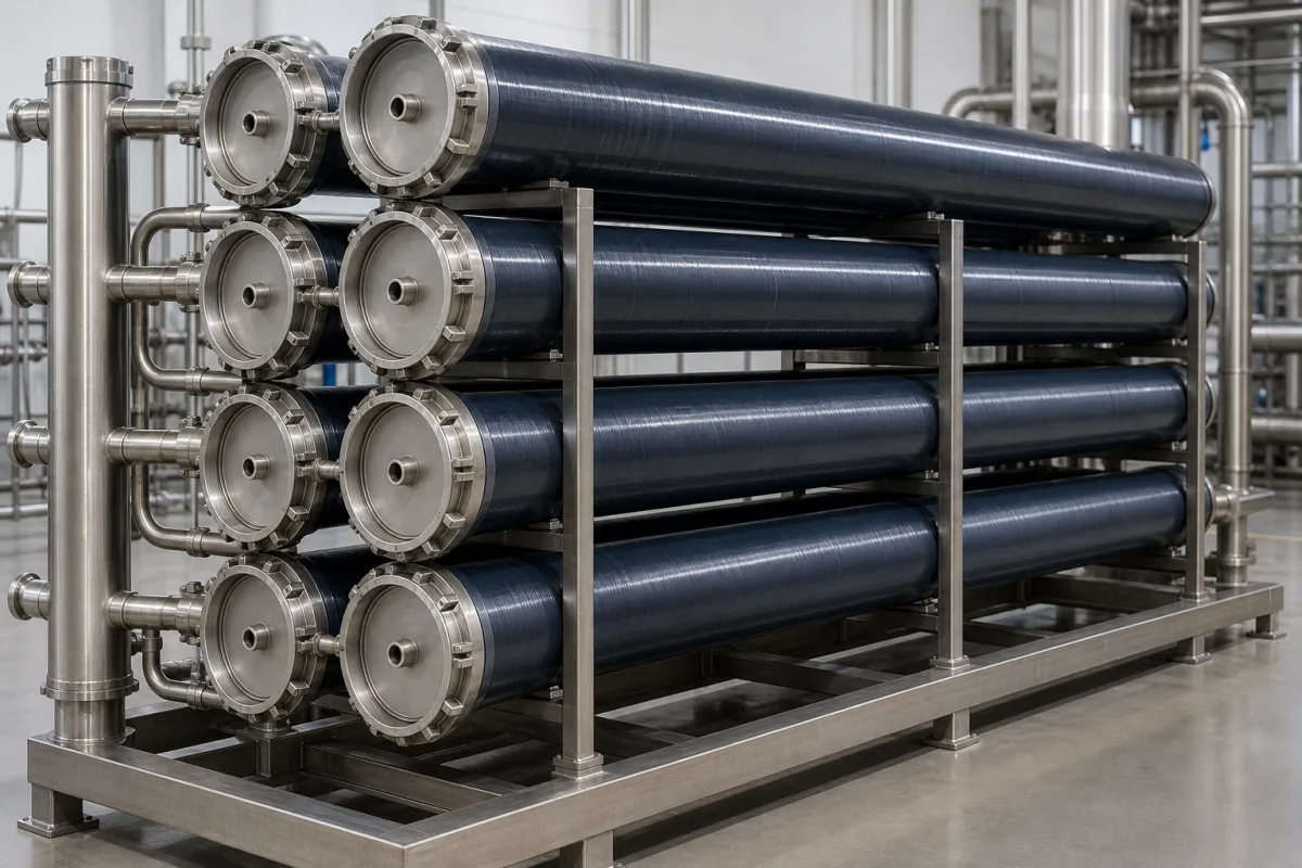
Representative product image. Confirm appearance and specifications with the manufacturer.

Product Specifications

Technical details and manufacturing context for Pressure Vessels

Definition
In a Reverse Osmosis (RO) unit, pressure vessels are cylindrical housings that contain and support the semi-permeable membrane elements. They are engineered to withstand the high operating pressures required to force feedwater through the membranes, separating purified water (permeate) from concentrated brine (reject). Their primary role is to provide a secure, pressurized environment for the filtration process while protecting the delicate membrane elements from physical damage and contamination.

Pressure vessels are typically constructed from materials such as Fiberglass-Reinforced Plastic (FRP), Stainless Steel (e.g., 316L), or Duplex Stainless Steel, chosen for their corrosion resistance and mechanical strength. Standard diameters include 4-inch (approx. 101.6 mm), 8-inch (approx. 203.2 mm), and larger industrial sizes, with lengths typically ranging from 1 to 6 meters to accommodate multiple membrane elements in series. These dimensions are reference ranges; the exact specifications must be confirmed for the specific model and application.

When selecting a pressure vessel, key inputs include the required operating pressure, feedwater chemistry, temperature, and the number and type of membrane elements to be housed. The vessel must be compatible with the system's piping and connections, and its pressure rating must match the system's design. Verification questions for procurement include: What is the maximum allowable working pressure? What are the end connection types? What materials are wetted parts made of? Are there any specific standards or certifications required for the application?

Maintenance signals include visible corrosion, cracking, or leakage at seals or fittings. Failure boundaries are defined by the vessel's pressure rating and material limits; exceeding these can lead to catastrophic failure. Regular inspection and pressure testing are essential to ensure integrity. Always verify model-specific values and standards with the legal manufacturer or supplier.
Working Principle
The pressure vessel receives pressurized feedwater from the high-pressure pump. This water is forced longitudinally through the vessel, passing over the surface of the spiral-wound membrane elements housed inside. The applied pressure (typically 50-1000 psi, depending on application) overcomes the natural osmotic pressure, driving water molecules through the membrane while rejecting dissolved salts and contaminants. The purified permeate is collected centrally, while the concentrated reject stream exits the vessel's end.
Common Materials
Fiberglass-Reinforced Plastic (FRP), Stainless Steel (e.g., 316L), Duplex Stainless Steel
Technical Parameters

What to specify in your RFQ

  • Standard diameters include 4-inch (approx. 101.6 mm), 8-inch (approx. 203.2 mm), and larger industrial sizes, with lengths typically ranging from 1 to 6 meters to accommodate multiple membrane elements in series. in mm

These are the quantities to specify to the manufacturer when sizing or requesting a quote. The manufacturer's own documentation governs the exact figures and applicable standard.

Components / BOM
  • Cylindrical Shell
    The main body that contains the internal pressure and houses the membrane elements.
    Material: FRP or Stainless Steel
  • End Cap / Head Part
    Seals the ends of the vessel, often containing ports for feed inlet, concentrate outlet, and permeate collection tube.
    Material: FRP, Stainless Steel, or Engineering Plastic
  • Permeate Tube
    A central tube running the length of the vessel that collects purified water (permeate) from the membrane elements and channels it out of the vessel.
    Material: PVC, ABS, or Stainless Steel
  • Interconnector / Adapter Part
    Seals and connects adjacent membrane elements inside the vessel, ensuring proper flow from one element to the next.
    Material: ABS or Polypropylene
  • Anti-Telescoping Device (ATD)
    Prevents the stack of membrane elements from being pushed downstream under high pressure, which could damage the elements.
    Material: FRP or Plastic

Applied To / Applications

This component is essential for the following industrial systems and equipment:

Industrial Ecosystem & Supply Chain Structure

Complementary Systems
Downstream Applications
Specialized Tooling

Application Fit & Sizing Matrix

Operational Limits
pressure: Up to 1200 psi (82.7 bar) for standard vessels, higher for specialized applications
flow rate: Vessel-dependent: typically 5-100 GPM per vessel (19-379 L/min)
other spec: pH range: 2-11 (cleaning), 4-10 (continuous operation)
temperature: 5°C to 45°C (typical RO operation range)
slurry concentration: Not applicable for RO membranes (solids-free feed required)
Media Compatibility
✓ Potable water treatment ✓ Brackish water desalination ✓ Industrial process water purification
Unsuitable: High-viscosity fluids or abrasive slurries (causes membrane fouling/damage)
Sizing Data Required
  • Required permeate flow rate (GPM or m³/day)
  • Feed water quality/TDS (mg/L)
  • System recovery rate (%)

Reliability & Engineering Risk Analysis

Failure Mode & Root Cause
Stress Corrosion Cracking (SCC)
Cause: Combination of tensile stress (residual or applied) and corrosive environment (e.g., chlorides, sulfides, caustics) leading to crack initiation and propagation, often at welds or high-stress areas.
Creep Rupture
Cause: Time-dependent deformation under sustained high temperature and pressure, leading to microstructural changes, void formation, and eventual rupture, typically in high-temperature applications above design limits.
Maintenance Indicators
  • Visible bulging, distortion, or localized swelling on the vessel shell or head indicating overpressure or material degradation.
  • Audible hissing, whistling, or popping sounds from relief valves, seams, or connections suggesting leaks, overpressure, or imminent failure.
Engineering Tips
  • Implement a robust corrosion monitoring program using techniques like ultrasonic thickness testing (UTT) and internal inspection to track wall thinning and schedule timely repairs.
  • Ensure proper pressure relief system maintenance by regularly testing and calibrating safety valves and rupture discs to prevent overpressure scenarios and comply with ASME Boiler and Pressure Vessel Code standards.

Indicative industry ranges for design and RFQ preparation. Confirm the exact figures and applicable standard with the manufacturer before specifying.

Compliance & Manufacturing Standards

Applicable Standards
ISO 16528-1:2019 - Boilers and pressure vessels ASME Boiler and Pressure Vessel Code (BPVC) Section VIII EN 13445:2021 - Unfired pressure vessels

Quoted from the published standard.

Manufacturing Precision
  • Wall thickness: +/-10% of nominal thickness
  • Circumferential weld misalignment: ≤ 1.5mm or 10% of thinner plate thickness
Quality Inspection
  • Hydrostatic pressure test
  • Radiographic testing (RT) of welds

Manufacturers of Pressure Vessels

Manufacturer profiles associated with Pressure Vessels.

Sourcing Pressure Vessels from China?
Tell us your specification and target quantity — we will match it against manufacturer records and come back with the factories that fit.
Request manufacturers We manufacture this

Manufacturer listings support early research and capability understanding. They are not certification, ranking, or transaction guarantees.

Technical documentation
Request current drawings, revision history, and a signed specification sheet.
Manufacturing capability
Verify equipment lists, process limits, capacity, and representative production evidence.
Inspection readiness
Confirm test methods, calibrated equipment, sampling plans, and traceable reports.
Supplier transparency
Check the legal entity, factory address, ownership, certifications, and direct contacts.

CNFX does not score or rank suppliers. Buyers must verify all claims and documents with the legal manufacturer before ordering.

Supply Chain Compatible Machinery & Devices

Automated Powder Coating System

Integrated industrial system for applying dry powder coatings to metal substrates.

Explore Specs →
Centrifugal Pump Impeller

The centrifugal pump impeller is a critical rotating component that converts mechanical energy from the motor into kinetic energy in fluid systems.

Explore Specs →
High-Precision CNC Laser Cutting Machine

Computer-controlled industrial machine using focused laser beams to cut sheet metal with micron-level accuracy.

Explore Specs →
Industrial-Grade Hydraulic Cylinder Piston Rod

This industrial-grade piston rod is a precision-ground cylindrical component designed for use in hydraulic cylinders.

Explore Specs →

Frequently Asked Questions

What materials are pressure vessels made of?

Common materials include Fiberglass-Reinforced Plastic (FRP), Stainless Steel (e.g., 316L), and Duplex Stainless Steel. The choice depends on the application's corrosion and pressure requirements.

What are typical dimensions of RO pressure vessels?

Standard diameters include 4-inch (approx. 101.6 mm), 8-inch (approx. 203.2 mm), and larger industrial sizes. Lengths typically range from 1 to 6 meters to accommodate multiple membrane elements in series. Confirm exact dimensions for your model.

How do I select the right pressure vessel?

Consider operating pressure, feedwater chemistry, temperature, and the number/type of membrane elements. Ensure the vessel's pressure rating and connections match your system. Verify all specifications with the manufacturer.

What maintenance is required?

Regularly inspect for corrosion, cracking, or leaks at seals and fittings. Perform pressure testing as recommended. Follow the manufacturer's guidelines for inspection intervals and replacement criteria.

Data Basis

Editorial classification, named public sources where available, and source-reviewed manufacturer records.

Preliminary Technical Classification
This page supports structured research, RFQ preparation, and supplier evaluation. It does not replace buyer-led supplier qualification, standards review, or technical approval.
Buyer enquiry

Request manufacturing insight for Pressure Vessels

Ask for use case, specification boundaries, supplier type, and RFQ preparation information for this product.

Where it goes
Straight to the CNFX editorial desk, and to the manufacturer if this product is linked to a claimed profile. Nothing is broadcast to a supplier list.
Your details stay here
We do not sell or rent enquiry data, and we do not add you to a mailing list. Used only to answer this request.
No commission, no middleman
CNFX is a directory. We take no cut of any order and never negotiate on a supplier's behalf.
What we don't claim
A listing is not an endorsement. Qualify every supplier and verify every figure yourself before ordering.

Your business information is used only to process this request.

Thank you! Your message has been sent. We'll respond within 1–3 business days.
Sorry, we couldn't send your message. Please try again, or email us at contact@cnfx.com.

Need to Manufacture Pressure Vessels?

Compare manufacturer profiles with relevant product and process capability.

Previous Product
Z-axis Ram/Spindle
Last Product
Get QuotesChat