Editorial Technical Reference

Safety Interlock Controller

This page explains how Safety Interlock Controller is classified within Machinery and Equipment Manufacturing. Technical values and manufacturer relationships are research references; confirm the current specification and supplier evidence for each order.

Technical Definition & Core Assembly

A safety-critical control component that prevents hazardous machine operations by enforcing logical dependencies between system states.
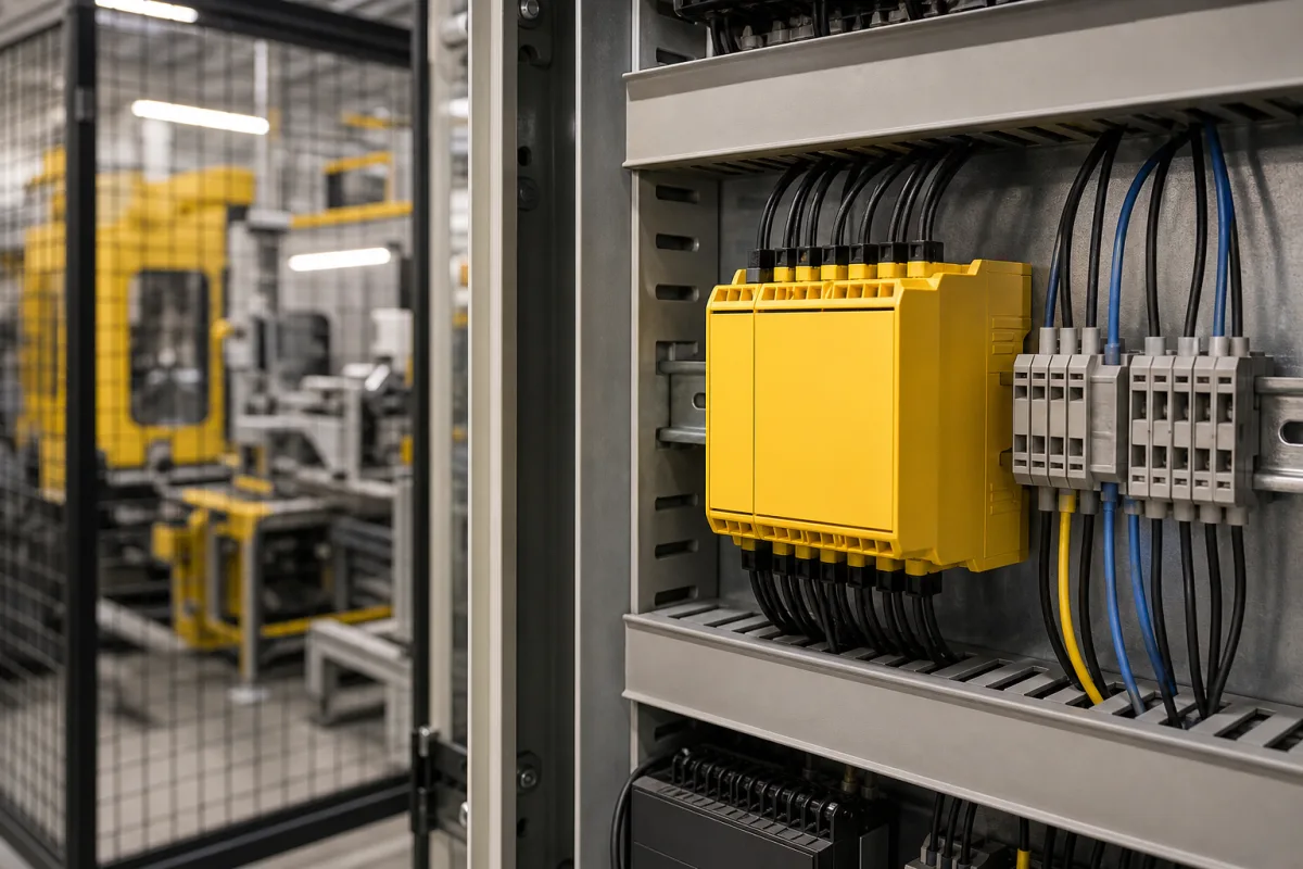
Representative product image. Confirm appearance and specifications with the manufacturer.

Product Specifications

Technical details and manufacturing context for Safety Interlock Controller

Definition
Within a Centralized Control System, the Safety Interlock Controller is a dedicated hardware or software module responsible for monitoring safety conditions and enforcing interlock logic. It ensures that potentially dangerous machine functions (e.g., starting a press, opening a high-voltage cabinet) can only be initiated when all prerequisite safety conditions are met (e.g., guards are closed, personnel are clear, energy is isolated). It acts as the final logic gate in the safety chain, overriding standard operational commands to prevent accidents. The controller continuously monitors inputs from safety devices such as emergency stop buttons, safety light curtains, door switches, and pressure mats. It processes these signals against a pre-programmed safety logic, often compliant with standards like ISO 13849-1. If all required safety conditions are TRUE, it enables a safe output signal (often a safety relay contact or a validated safety message over a network) that permits the hazardous function. If any monitored condition becomes FALSE, it immediately and forcibly disables the output, bringing the system to a safe state. The device is designed for integration into machinery and equipment manufacturing, with a rated voltage of 24 V DC ±10% (per IEC 61131-2), power consumption ≤5 W, 8 safety inputs and 4 safety outputs (expandable via modular units), and a Safety Integrity Level of SIL 3 (per IEC 61508). Response time from input change to output de-energization is ≤20 ms (per IEC 61784-3). Operating temperature range is -25 to 70 °C, storage -40 to 85 °C (per IEC 60068-2-1/2), relative humidity 10–95% non-condensing (per IEC 60068-2-78), and degree of protection IP54–IP65 (per IEC 60529). Housing material is PA66 (flame-retardant, halogen-free, UL 94 V-0). Weight is 0.5–1.2 kg, dimensions 45×100×115 mm (DIN rail mount). These values are directory references; verify model-specific values and standards with the legal manufacturer or supplier.
Working Principle
The controller continuously monitors inputs from safety devices (e.g., emergency stop buttons, safety light curtains, door switches, pressure mats). It processes these signals against a pre-programmed safety logic (often compliant with standards like ISO 13849-1). If all required safety conditions are TRUE, it enables a safe output signal (often a safety relay contact or a validated safety message over a network) that permits the hazardous function. If any monitored condition becomes FALSE, it immediately and forcibly disables the output, bringing the system to a safe state.
Common Materials
Printed Circuit Board (PCB), Electronic Components (ICs, relays, connectors), Plastic/Steel Enclosure
Technical Parameters
ParameterTypical rangeNotes & selection driver
Rated Voltage24 ±10% V DCOperation outside this range may cause malfunctionIEC 61131-2
Power Consumption≤5 WIncludes all internal logic and output drivers
Number of Safety Inputs8 channelsExpandable via modular units
Number of Safety Outputs4 channelsRelay or solid-state, configurable
Safety Integrity LevelSIL 3Suitable for high-risk machineryIEC 61508
Response Time≤20 msFrom input change to output de-energizationIEC 61784-3
Operating Temperature-25–70 °CExtended range availableIEC 60068-2-1/2
Storage Temperature-40–85 °CNon-operationalIEC 60068-2-1/2
Relative Humidity10–95 % RHNon-condensingIEC 60068-2-78
Degree of ProtectionIP54–IP65Depends on enclosure optionIEC 60529
Housing MaterialPA66Flame-retardant, halogen-freeUL 94 V-0
Weight0.5–1.2 kgDepends on configuration
Dimensions (W×H×D)45×100×115 mmDIN rail mount

Ranges are indicative industry figures for RFQ preparation, not a supplier commitment. Confirm every value and standard with the legal manufacturer before ordering.

Components / BOM
  • Processor/Logic Solver
    Executes the pre-programmed safety logic, evaluating input states to determine output states.
    Material: Silicon (Integrated Circuit)
  • Input Interface Circuitry
    Conditions and monitors signals from connected safety devices (e.g., E-Stops, safety switches).
    Material: Electronic Components (resistors, capacitors, opto-isolators)
  • Safety Output Relays
    Physically interrupts power to hazardous machine functions upon a safety fault. Often features forced-guided contacts for reliability monitoring.
    Material: Copper, Steel, Plastic
  • Diagnostic LEDs/Display Part
    Provides visual status indication (e.g., power, fault, input/output status) for troubleshooting.
    Material: Plastic, LEDs

Applied To / Applications

This component is essential for the following industrial systems and equipment:

Industrial Ecosystem & Supply Chain Structure

Complementary Systems
Downstream Applications
Specialized Tooling

Application Fit & Sizing Matrix

Operational Limits
pressure: 0.5 to 10 bar (operating range), 15 bar (max burst)
other spec: IP67 ingress protection, 24V DC ±10% power, SIL 3/PLe safety rating
temperature: -20°C to +70°C (operating), -40°C to +85°C (storage)
Media Compatibility
✓ Industrial control panels (dry environments) ✓ Hydraulic/pneumatic machine interfaces ✓ Clean electrical cabinet installations
Unsuitable: Direct exposure to high-pressure washdown or corrosive chemical splashes
Sizing Data Required
  • Number of safety inputs/outputs required
  • Required safety integrity level (SIL/PL)
  • Control system communication protocol compatibility

Reliability & Engineering Risk Analysis

Failure Mode & Root Cause
Sensor drift or calibration loss
Cause: Environmental factors (temperature fluctuations, humidity, dust accumulation) causing gradual deviation from setpoints, or aging of sensing elements leading to inaccurate readings.
Controller logic failure
Cause: Software corruption due to power surges, electromagnetic interference, or memory degradation, or hardware faults in microprocessors/relays causing incorrect safety decisions.
Maintenance Indicators
  • Intermittent or false safety trips without apparent process deviations
  • Unresponsive or delayed controller feedback to manual test inputs
Engineering Tips
  • Implement regular functional testing with calibrated instruments to verify sensor accuracy and response times, documenting trends for predictive maintenance.
  • Install surge protection and EMI shielding on power and signal lines, and maintain environmental controls (stable temperature/humidity) in controller enclosures.

Indicative industry ranges for design and RFQ preparation. Confirm the exact figures and applicable standard with the manufacturer before specifying.

Compliance & Manufacturing Standards

Applicable Standards
ISO 13849-1: Safety of machinery - Safety-related parts of control systems ANSI/UL 508: Industrial Control Equipment EN 60947-5-1: Low-voltage switchgear and controlgear - Control circuit devices and switching elements

Quoted from the published standard.

Manufacturing Precision
  • Enclosure IP rating: IP65 minimum
  • Response time: +/- 10ms from actuation to output signal
Quality Inspection
  • Functional Safety Test (PL/SIL verification)
  • Environmental Sealing Test (IP rating verification)

Manufacturers of Safety Interlock Controller

Manufacturer profiles associated with Safety Interlock Controller.

Sourcing Safety Interlock Controller from China?
Tell us your specification and target quantity — we will match it against manufacturer records and come back with the factories that fit.
Request manufacturers We manufacture this

Manufacturer listings support early research and capability understanding. They are not certification, ranking, or transaction guarantees.

Technical documentation
Request current drawings, revision history, and a signed specification sheet.
Manufacturing capability
Verify equipment lists, process limits, capacity, and representative production evidence.
Inspection readiness
Confirm test methods, calibrated equipment, sampling plans, and traceable reports.
Supplier transparency
Check the legal entity, factory address, ownership, certifications, and direct contacts.

CNFX does not score or rank suppliers. Buyers must verify all claims and documents with the legal manufacturer before ordering.

Supply Chain Compatible Machinery & Devices

Automated Powder Coating System

Integrated industrial system for applying dry powder coatings to metal substrates.

Explore Specs →
Centrifugal Pump Impeller

The centrifugal pump impeller is a critical rotating component that converts mechanical energy from the motor into kinetic energy in fluid systems.

Explore Specs →
High-Precision CNC Laser Cutting Machine

Computer-controlled industrial machine using focused laser beams to cut sheet metal with micron-level accuracy.

Explore Specs →
Industrial-Grade Hydraulic Cylinder Piston Rod

This industrial-grade piston rod is a precision-ground cylindrical component designed for use in hydraulic cylinders.

Explore Specs →

Frequently Asked Questions

What is the purpose of a Safety Interlock Controller?

It prevents hazardous machine operations by ensuring that dangerous functions can only be activated when all safety conditions are met, such as guards closed and personnel clear.

What safety devices can be connected to the inputs?

Typical inputs include emergency stop buttons, safety light curtains, door switches, and pressure mats. The controller monitors these to determine if it is safe to operate.

What does SIL 3 mean for this controller?

SIL 3 (Safety Integrity Level 3) per IEC 61508 indicates a high level of risk reduction capability, suitable for high-risk machinery. It is a design reference; actual certification must be verified with the manufacturer.

How fast does the controller respond to a safety event?

The response time from input change to output de-energization is ≤20 ms per IEC 61784-3. This ensures rapid shutdown to a safe state.

Data Basis

Editorial classification, named public sources where available, and source-reviewed manufacturer records.

Preliminary Technical Classification
This page supports structured research, RFQ preparation, and supplier evaluation. It does not replace buyer-led supplier qualification, standards review, or technical approval.
Buyer enquiry

Request manufacturing insight for Safety Interlock Controller

Ask for use case, specification boundaries, supplier type, and RFQ preparation information for this product.

Where it goes
Straight to the CNFX editorial desk, and to the manufacturer if this product is linked to a claimed profile. Nothing is broadcast to a supplier list.
Your details stay here
We do not sell or rent enquiry data, and we do not add you to a mailing list. Used only to answer this request.
No commission, no middleman
CNFX is a directory. We take no cut of any order and never negotiate on a supplier's behalf.
What we don't claim
A listing is not an endorsement. Qualify every supplier and verify every figure yourself before ordering.

Your business information is used only to process this request.

Thank you! Your message has been sent. We'll respond within 1–3 business days.
Sorry, we couldn't send your message. Please try again, or email us at contact@cnfx.com.

Need to Manufacture Safety Interlock Controller?

Compare manufacturer profiles with relevant product and process capability.

Previous Product
Z-axis Ram/Spindle
Last Product
Get QuotesChat