Editorial Technical Reference

Servo Drive Amplifier

This page explains how Servo Drive Amplifier is classified within Machinery and Equipment Manufacturing. Technical values and manufacturer relationships are research references; confirm the current specification and supplier evidence for each order.

Technical Definition & Core Assembly

Electronic power amplifier that controls and drives servo motors within a servo drive system.
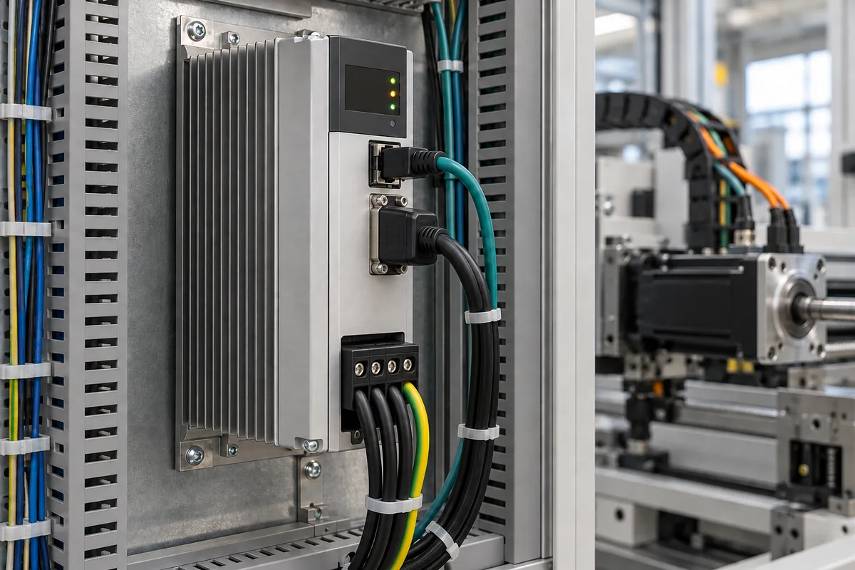
Representative product image. Confirm appearance and specifications with the manufacturer.

Product Specifications

Technical details and manufacturing context for Servo Drive Amplifier

Definition
A servo drive amplifier is a critical electronic component within a servo drive system that receives low-power control signals from the controller and amplifies them into high-power electrical currents to precisely drive and control the motion of a servo motor. It regulates torque, speed, and position by modulating voltage and current to the motor windings. The amplifier is designed for use in machinery and equipment manufacturing, where precise motion control is essential. It is a component-level product, typically integrated into a larger servo drive system. The amplifier's rated power ranges from 0.4 to 15 kW, matching the motor size. It operates on a three-phase supply voltage of 200–480 V AC. Continuous output current is 2–100 A RMS per phase, with peak output current of 4–200 A for a 3-second overload. Control accuracy is ±0.01% for speed regulation, and frequency response is 1–3 kHz closed-loop bandwidth. Operating temperature is -10 to 50°C, with derating above 40°C; storage temperature is -40 to 85°C. Protection class is IP20 to IP54 (IP54 with option) per IEC 60529. Cooling is forced air flow of 0.5–2.5 m³/min. Weight ranges from 2 to 25 kg, and dimensions vary by model: 100–300 mm width, 200–500 mm height, 150–400 mm depth. Materials include silicon for semiconductors, copper for windings and traces, aluminum for heat sinks, epoxy resin for PCB substrate, and plastic for housing. These values are directory reference ranges and must be confirmed for the specific model and application. Verify all specifications and standards with the legal manufacturer or supplier before procurement.
Working Principle
The amplifier receives command signals (typically pulse, analog voltage, or digital communication) specifying the desired motor position, speed, or torque. It compares this command with feedback signals (from encoders or resolvers on the motor) to calculate an error. Using this error, its internal control loops (current, velocity, position) generate Pulse Width Modulation (PWM) signals. These PWM signals drive power transistors (like IGBTs or MOSFETs) in an H-bridge configuration to switch high DC bus voltage, creating a controlled AC waveform (voltage and frequency) that is supplied to the servo motor, causing precise rotational movement.
Common Materials
Silicon (for semiconductors), Copper (for windings/traces), Aluminum (for heat sinks), Epoxy resin (for PCB substrate), Plastic (for housing)
Technical Parameters
ParameterTypical rangeNotes & selection driver
Rated Power0.4–15 kWMatches motor size
Supply Voltage200–480 V AC3-phase input
Continuous Output Current2–100 ARMS per phase
Peak Output Current4–200 AFor 3 s overload
Control Accuracy±0.01 %Speed regulation
Frequency Response1–3 kHzClosed-loop bandwidth
Operating Temperature-10–50 °CDerate above 40°C
Storage Temperature-40–85 °CNon-condensing
Protection ClassIP20–IP54IP54 with optionIEC 60529
Cooling Method0.5–2.5 m³/minForced air flow
Weight2–25 kgDepends on power
Dimensions (W×H×D)100–300×200–500×150–400 mmVaries by model

Ranges are indicative industry figures for RFQ preparation, not a supplier commitment. Confirm every value and standard with the legal manufacturer before ordering.

Components / BOM
  • Power Stage (H-Bridge)
    Contains power transistors (IGBTs/MOSFETs) that switch the DC bus voltage to generate the AC output for the motor.
    Material: Silicon semiconductors, copper
  • Control Board (PCB)
    Processes command and feedback signals, runs control algorithms, and generates PWM signals for the power stage.
    Material: Epoxy resin (substrate), copper traces, electronic components
  • Heat Sink Part
    Dissipates heat generated by the power transistors to prevent overheating and ensure reliability.
    Material: Aluminum
  • DC Bus Capacitors Part
    Store and smooth the rectified DC voltage from the power supply, providing stable energy for the power stage.
    Material: Aluminum electrolytic materials
  • Communication Ports Part
    Physical connectors for control signals, feedback signals, and network communication.
    Material: Plastic, metal contacts

Applied To / Applications

This component is essential for the following industrial systems and equipment:

Industrial Ecosystem & Supply Chain Structure

Complementary Systems
Downstream Applications
Specialized Tooling

Application Fit & Sizing Matrix

Operational Limits
pressure: Not applicable (electronic component)
other spec: Humidity: 5-95% non-condensing, Vibration: 5-2000 Hz at 2G max
temperature: -10°C to +40°C (operating), -20°C to +70°C (storage)
Media Compatibility
✓ Industrial automation systems ✓ CNC machinery ✓ Robotic arms
Unsuitable: High-voltage arc welding environments
Sizing Data Required
  • Motor power rating (kW)
  • Supply voltage (VAC/VDC)
  • Control signal type (analog/digital)

Reliability & Engineering Risk Analysis

Failure Mode & Root Cause
Overheating and thermal shutdown
Cause: Inadequate cooling due to dust accumulation on heatsinks, blocked ventilation, or excessive ambient temperatures leading to component degradation and protective shutdowns.
Power stage failure (IGBT/MOSFET damage)
Cause: Voltage spikes from poor power quality, improper grounding, or regenerative energy not properly dissipated through braking resistors, causing semiconductor breakdown.
Maintenance Indicators
  • Audible high-pitched whining or buzzing from the drive, indicating potential capacitor or switching component issues
  • Visible discoloration, bulging, or leaking capacitors on the circuit board, signaling imminent failure
Engineering Tips
  • Implement regular preventive maintenance: Clean heatsinks and filters quarterly, monitor operating temperatures with infrared thermography, and ensure proper airflow around the drive.
  • Install line reactors or surge protectors on power input, use shielded cables for motor connections, and verify braking resistor circuits are correctly sized and functional to handle regenerative loads.

Indicative industry ranges for design and RFQ preparation. Confirm the exact figures and applicable standard with the manufacturer before specifying.

Compliance & Manufacturing Standards

Applicable Standards
ISO 13849-1:2015 Safety of machinery - Safety-related parts of control systems IEC 61800-5-1:2007 Adjustable speed electrical power drive systems - Safety requirements EN 61800-3:2018 Adjustable speed electrical power drive systems - EMC requirements and specific test methods

Quoted from the published standard.

Manufacturing Precision
  • Mounting surface flatness: ≤0.05mm per 100mm
  • Power terminal torque tolerance: ±10% of specified value
Quality Inspection
  • High-potential (hipot) insulation resistance test
  • Thermal cycling endurance test

Manufacturers of Servo Drive Amplifier

Manufacturer profiles associated with Servo Drive Amplifier.

Sourcing Servo Drive Amplifier from China?
Tell us your specification and target quantity — we will match it against manufacturer records and come back with the factories that fit.
Request manufacturers We manufacture this

Manufacturer listings support early research and capability understanding. They are not certification, ranking, or transaction guarantees.

Technical documentation
Request current drawings, revision history, and a signed specification sheet.
Manufacturing capability
Verify equipment lists, process limits, capacity, and representative production evidence.
Inspection readiness
Confirm test methods, calibrated equipment, sampling plans, and traceable reports.
Supplier transparency
Check the legal entity, factory address, ownership, certifications, and direct contacts.

CNFX does not score or rank suppliers. Buyers must verify all claims and documents with the legal manufacturer before ordering.

Supply Chain Compatible Machinery & Devices

Heavy-Duty CNC Plasma Cutting Machine

The Heavy-Duty CNC Plasma Cutting Machine is a standalone industrial device designed for cutting conductive metals such as steel, stainless steel, aluminum, and copper alloys.

Explore Specs →
Automated Powder Coating System

Integrated industrial system for applying dry powder coatings to metal substrates.

Explore Specs →
Centrifugal Pump Impeller

The centrifugal pump impeller is a critical rotating component that converts mechanical energy from the motor into kinetic energy in fluid systems.

Explore Specs →
High-Precision CNC Laser Cutting Machine

Computer-controlled industrial machine using focused laser beams to cut sheet metal with micron-level accuracy.

Explore Specs →

Frequently Asked Questions

What is the typical input signal for a servo drive amplifier?

Typical input signals include pulse trains, analog voltage (e.g., ±10 V), or digital communication protocols (e.g., fieldbus). These signals specify the desired position, speed, or torque.

How does the amplifier achieve precise control?

It uses closed-loop control with feedback from encoders or resolvers. The internal control loops (current, velocity, position) compare the command with feedback and adjust PWM signals to minimize error.

What are the key electrical specifications to consider?

Key specifications include rated power (0.4–15 kW), supply voltage (200–480 V AC), continuous output current (2–100 A RMS), and peak output current (4–200 A for 3 s overload). These must match the motor and application.

What environmental conditions can the amplifier operate in?

Operating temperature is -10 to 50°C (derate above 40°C), storage temperature is -40 to 85°C. Protection class ranges from IP20 to IP54 (with option). Cooling requires forced air flow of 0.5–2.5 m³/min.

Data Basis

Editorial classification, named public sources where available, and source-reviewed manufacturer records.

Preliminary Technical Classification
This page supports structured research, RFQ preparation, and supplier evaluation. It does not replace buyer-led supplier qualification, standards review, or technical approval.
Buyer enquiry

Request manufacturing insight for Servo Drive Amplifier

Ask for use case, specification boundaries, supplier type, and RFQ preparation information for this product.

Where it goes
Straight to the CNFX editorial desk, and to the manufacturer if this product is linked to a claimed profile. Nothing is broadcast to a supplier list.
Your details stay here
We do not sell or rent enquiry data, and we do not add you to a mailing list. Used only to answer this request.
No commission, no middleman
CNFX is a directory. We take no cut of any order and never negotiate on a supplier's behalf.
What we don't claim
A listing is not an endorsement. Qualify every supplier and verify every figure yourself before ordering.

Your business information is used only to process this request.

Thank you! Your message has been sent. We'll respond within 1–3 business days.
Sorry, we couldn't send your message. Please try again, or email us at contact@cnfx.com.

Need to Manufacture Servo Drive Amplifier?

Compare manufacturer profiles with relevant product and process capability.

Previous Product
Z-axis Ram/Spindle
Last Product
Get QuotesChat