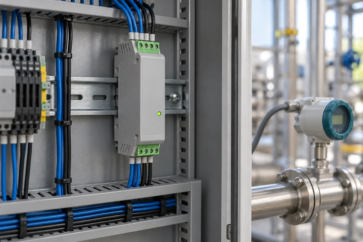
Frequency-to-analog signal converter for flowmeter pulse outputs (pulse to 4–20 mA)
Turning a flowmeter's pulse or frequency output into 4–20 mA for a PLC · input trigger levels, full-scale frequency, response time, output load and fault values
A turbine, paddlewheel or other pulse-output flowmeter reports rate as a pulse train whose frequency is proportional to flow, while the control system expects a 4–20 mA or 0–10 V signal. A frequency-to-analog converter sits between them on a DIN rail or in a field box: it conditions the pulses, measures their rate over a chosen time and drives a current or voltage proportional to it. The three things that decide whether it works on a given meter are the input stage (can it see the sensor's signal), the full-scale frequency and response time (how fast and how smooth the analog value is), and the output (load, isolation and what it does when pulses stop).
Frequency-, pulse- and rate-to-analog converters that accept a flowmeter's pulse output (magnetic pickup, open collector, TTL/CMOS or contact) and produce 0/4–20 mA or 0–5/0–10 V. DIN-rail analog conditioners and isolators for thermocouple, RTD, current and voltage inputs are covered on the Industrial signal conditioner page; strain-gauge amplifiers on the Load-cell signal conditioner page; pyrometer peak-and-hold processing on the Signal processor for mill pyrometers page. PWM duty-cycle-to-voltage modules, analog-to-pulse totaliser converters and flow computers are outside this page.
CNFX editorial research · Sources checked October 12, 2026 · 3 sources
Seeing the meter's pulses: 0.25/0.75 V trigger for magnetic pickups, 2.5/3.0 V for logic, sink or source pull resistors
Red Lion's IFMA takes switch contacts, CMOS or TTL outputs and magnetic pickups through a DIP-switch-selectable input. Its low-bias setting triggers at VIL = 0.25 V and VIH = 0.75 V for magnetic pickups, and its high-bias setting at 2.5 V and 3.0 V for logic signals; an internal 1 kΩ pull-down serves current-sourcing sensors (up to 24 mA at 24 V) and a 3.9 kΩ pull-up serves current-sinking sensors (up to 3 mA). [1] The maximum input signal is ±90 V with both resistors switched off, and the input impedance is at least 33 kΩ. [1]
Other converters assume a logic-level input. Brodie's Model 200 accepts TTL-compatible pulses with 'low' at +1.3 V and 'high' at +2.7 V and a maximum amplitude of ±100 V. [3] AW-Lake's FAC-R1 lists input amplitudes of 5 V to 24 V maximum. [2] Editorial note: a bare magnetic pickup produces a low-level AC signal, so check that the converter has a pickup-level input like the IFMA's low-bias setting, or put an amplifier between the pickup and a logic-level input.
Red Lion's installation guidance asks for shielded cable on all signal and control inputs, with the shield preferably connected only at the earthed DIN rail where the unit is mounted, or at both ends when the noise source is above 1 MHz. [1]
02
Full-scale frequency and response: from 5 ms plus one input period to a 1.1–3.6 s analog filter
The converter has to be scaled to the meter's frequency at full flow and has to average pulses to produce a steady output, and the three designs below do this differently. The IFMA's full scale can be set anywhere from 1 Hz to 25 kHz; it counts negative edges over a user-set minimum response time and averages them, so its actual response is that time plus up to one full input period, selectable from 5 ms + 1 period to 10 s + 1 period. [1] A separate maximum response time sets the low-frequency cut-out: if no new edge arrives in that time the output drops to the cut-out value. [1]
Editorial calculation: with the IFMA's shortest setting, a meter giving 2 Hz at the flow of interest has a 0.5 s period, so the output can take up to about 0.505 s to respond; at 1 kHz the period is 1 ms and the response is about 6 ms. Red Lion also notes that narrowing the span between the minimum and full-scale calibration values reduces accuracy in proportion. [1]
Analog output update 25 ms minimum; 16-bit output [2]
10-point linearisation table for non-linear meters [2]
Brodie Model 200
10 DIP-switch full-scale ranges from 12.5–25 Hz to 6400–12000 Hz [3]
Analog filter: 1.1 s time constant at 100 Ω load (2 s to 90%), 3.6 s at 500 Ω (8.5 s to 90%) [3]
0.2% of measured value; linearity better than 0.1% of full scale; drift 0.2% per 10 °C [3]
03
Output load, isolation and what happens when the pulses stop: 500 Ω compliance, 2200 V isolation, 20.5 mA over-range and 22 mA error
The IFMA drives 0–20 mA or 4–20 mA through a maximum 500 Ω load (10 VDC), or 0–5 V and 0–10 V at 10 mA, with 5 µA current resolution; it isolates power, input and output from each other, with a dielectric withstand of 2200 V between power and input and power and output, and 500 V between input and output, for 1 minute. [1] It runs from 85–250 VAC or 9–32 VDC, from 0 to 50 °C. [1]
AW-Lake's FAC-R1, powered from 10–28 VDC and rated −40 to 85 °C ambient, limits its standard output to +2.5% of maximum scaling (20.5 mA, 5.125 V or 10.25 V) and signals an error at +10% (22 mA, 5.5 V or 11 V), keeping over-range and error at separate levels. [2] Brodie's Model 200 drives 4–20 mA into a maximum of 500 Ω (10 V), adds a repeater pulse output at the input frequency and a 12 VDC, 120 mA supply for the sensor, and runs from 110 or 220 VAC between 0 and 50 °C. [3]
Editorial calculation: the 500 Ω limit at 20 mA is 0.5 kΩ × 0.02 A = 10 V of loop voltage, which is the compliance both the IFMA and the Model 200 state; add up the PLC input and any indicator in the loop against it.
04
Data for a frequency-to-analog converter enquiry
Paste it into your enquiry below or into an email to a maker, then replace every bracket.
Meter: [type; pulse output: magnetic pickup, open collector sinking or sourcing, TTL, contact; K-factor]
Range: [frequency at zero and full flow; lowest flow to be shown]
Response: [update time; averaging; low-flow cut-out time]
Output: [4–20 mA, 0–20 mA, 0–10 V; loop load; over-range and fault values]
Isolation and power: [isolation required; supply AC or DC]
Mounting: [DIN rail, panel or field enclosure; ambient temperature]
Explore company information and manufacturing capabilities, then discuss the scope of your project with a relevant supplier.
Share this page
Compiled and source-reviewed by the CNFX editorial team.
Each manufacturer above links to the page on that company's own website where the product is listed, with the date we checked it. How we source and review
· Page last updated 13 October 2026
Buyer questions
Can a frequency-to-analog converter read a magnetic pickup directly?
Some can. Red Lion's IFMA has a low-bias input triggering at 0.25 V and 0.75 V for magnetic pickups; converters with only TTL-level inputs, such as Brodie's Model 200 (1.3 V low, 2.7 V high), need a logic-level signal. [1][3]
How fast does the 4–20 mA output follow the flow?
It depends on the averaging: the IFMA responds in its set time plus up to one input period (5 ms + 1 period at the fastest), the FAC-R1 updates every 25 ms at minimum, and Brodie's Model 200 has a 1.1 s time constant at 100 Ω. [1][2][3]
What does the output do when the meter stops?
The IFMA drops its output to a low-frequency cut-out value when no edge arrives within the set maximum response time; AW-Lake's FAC-R1 signals an error at 22 mA (+10% of scaling). [1][2]
What loop load can the converter drive?
Red Lion's IFMA and Brodie's Model 200 both state 20 mA into a maximum of 500 Ω, or 10 V. [1][3]
Sources and what still needs a direct check
Sources checked 2026-10-12. Input, range, response, output and isolation figures come from Red Lion's IFMA bulletin, AW-Lake's FAC-R1 data sheet and Brodie's Model 200 design specification. Values apply to the models named.