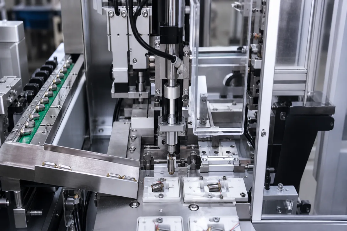
Vibration motor insertion unit: the low-force servo press station that seats cylindrical ERM motors into holders, rubber boots or housings
Automatic station module · small servo press pushing 3.4 to 7 mm cylindrical ERM motors into holders, boots or housings on pallet nests, with force and position recorded for each part
In an automatic assembly line, one station has a single job: take a small cylindrical vibration motor, hold it so the eccentric weight on its shaft is free, and push its can into a holder, a rubber boot or a moulded pocket until it seats. The parts are a few millimetres across, so the station is built around a low-force electric press with a force sensor, a nest that locates the receiving part, and a feed that presents each motor the same way round. What the station records for each part, force against position, is what proves the motor went fully home without being crushed.
Insertion or press-in stations for cylindrical ERM vibration motors in automatic assembly: the low-force servo press or press actuator, its force sensing and per-part records, the motor feed and gripper, the nest, and how the motor's size and mounting method set the job. Complete rotary-dial assembly and 100 g jig test cells for massager motor modules are covered on the Vibration motor module assembly and test cell page; the motors themselves on the Vibration motor (ERM core) page; general robot arms used for assembly on the Assembly robot and Robotic manipulator pages; electromechanical servo press modules across force ranges on the Servo motor actuator for press-fitting page.
CNFX editorial research · Sources checked October 13, 2026 · 4 sources
3.4 to 7 mm motor cans, eccentric weight beyond the body, and boots that add up to 1.0 mm
Vybronics' table of cylindrical ERM motors shows the size range an insertion unit has to cover. Bodies run from 3.4 mm diameter and 6.55 mm long (VZ30C1T8219732L, 11.0 mm overall) through 4 mm and 6 mm types to 7.0 mm diameter and 16.5 mm long (VZ7AL2B1692082, 24.9 mm overall). Its mounting configurations include plain wire leads, PCB brackets, through-hole and SMD types, spring contacts, encapsulated motors and Config 17, a wire-lead motor in a rubber boot; it offers connectors and rubber sleeves or boots as additions to leaded parts, though not to every one. [1]
Editorial calculation: on the three rubber-boot types listed, the second figure Vybronics gives (Dia / Hgt) is 0.5 mm (4.0 to 4.5 mm), 1.0 mm (4.0 to 5.0 mm) and 0.7 mm (6.0 to 6.7 mm) larger than the body diameter, which is what the boot adds across the motor; overall length exceeds body length by 3.9 to 8.4 mm across the table. The gripper and push tool have to act on the can or boot without loading the part that sticks out beyond the body, so ask the station builder to show where the tool touches the motor.
Give the station builder the motor drawing, the boot or holder drawing with its interference, the receiving part and its nest, and the orientation in which motors arrive from the feeder or tray.
02
A 0.25 kN servo press with a 0.05 kN range, and what gets recorded for each motor
Kistler's NCFT 2157B1 electromechanical joining module is a servo press for processes with low forces, with a piezoelectric force sensor and measuring ranges of 0.25 kN and 0.05 kN, a 100 mm stroke, a maximum speed of 400 mm/s, a holding brake and a straight drive; Kistler lists 3C electronics manufacturing, electrical and electronics, medical and semiconductor work among its applications. [2]
IAI offers servo-press rod actuators with a built-in load cell in a range from 2 kg to 5 t (50,000 N) of thrust, states a load repeatability of ±0.5 %, and says each pressing step is set by entering position, speed, acceleration and load, followed by a pressing judgement condition. Its controller outputs processing history, position in mm and load in N, to a PLC, computer or display without an external load cell, encoder or PLC. [3]
Editorial calculation: at Kistler's 400 mm/s maximum, a 20 mm approach stroke above the nest takes 0.05 s, so cycle time is set by the slow final pressing stroke, feeding and transfer rather than by the approach. Where a module offers two ranges, such as 0.25 kN and 0.05 kN, ask the builder which range the judgement window runs in for your boot or holder.
Ask for the force and position window that accepts a seated motor, what happens to a rejected part, and how the force–position curve for each motor is stored and linked to its serial or tray position.
03
Moulded pockets, cradles and clips: which mounts are pressed and which are fixed another way
Precision Microdrives' guide to mounting vibration motors on PCBs groups the methods as solder (through-hole pins, surface mount reflow), glue and adhesive, fasteners and clips, and injection-moulded mounts. In a moulded mount the motor body is held in an injection-moulded plastic housing screwed to the PCB, optionally secured with a low-blooming epoxy or silicone filler; in a spring-pad mounting the enclosure moulding acts as the housing and the motor is pinned against the board. [4]
For cylindrical motors held in a moulded or machined cradle, Precision Microdrives says the cradle has to fit the motor closely, because any movement turns into lost vibration strength and audible noise, and that a loose fixing can let the motor work its way free. It warns against low-viscosity cyanoacrylate, which can enter the motor and glue its mechanism, and recommends a high-viscosity epoxy or hot-melt instead. [4] Editorial note: where a station dispenses adhesive before pressing, the dispense and press steps belong in the same force–position record, so a motor pressed into a dry pocket can be caught.
04
What to send for a vibration motor insertion station
Paste it into your enquiry below or into an email to a maker, then replace every bracket.
Motor: [part number; diameter; body and overall length; leads, springs or SMD]
Mount: [rubber boot; moulded pocket; cradle; interference]
Receiving part: [housing or board; nest design; tolerance]
Feed: [tray, tube or vibratory feeder; orientation]
Press: [force range; stroke; speed; force and position window]
Records: [curve storage; traceability; reject handling]
Rate: [parts per hour; manual load or automatic line]
Explore company information and manufacturing capabilities, then discuss the scope of your project with a relevant supplier.
Share this page
Compiled and source-reviewed by the CNFX editorial team.
Each manufacturer above links to the page on that company's own website where the product is listed, with the date we checked it. How we source and review
· Page last updated 13 October 2026
Buyer questions
How large are the motors an insertion unit handles?
In Vybronics' cylindrical range, from 3.4 mm diameter and 6.55 mm long to 7.0 mm diameter and 16.5 mm long, 11.0 to 24.9 mm overall. [1]
How much force range does the press need?
Low: Kistler's NCFT 2157B1 for low-force processes has ranges of 0.25 kN and 0.05 kN with a 100 mm stroke. [2]
What does the press record?
IAI's servo press controller outputs position in mm and load in N for each pressing, and applies a pressing judgement condition. [3]
Can motors be glued instead of pressed?
Precision Microdrives lists adhesive mounting but warns against low-viscosity cyanoacrylate, which can enter the motor; it recommends high-viscosity epoxy or hot-melt. [4]
Sources and what still needs a direct check
Sources checked 2026-10-13. Vybronics' parametric table of cylindrical ERM motors and mounting configurations, Kistler's NCFT 2157B1 joining module page, IAI's servo-press ROBO Cylinder page, and Precision Microdrives' application bulletin AB-006 on mounting vibration motors to PCBs.