Editorial Technical Reference

Digital Audio Signal Processor Module

This page explains how Digital Audio Signal Processor Module is classified within Manufacture of Consumer Electronics. Technical values and manufacturer relationships are research references; confirm the current specification and supplier evidence for each order.

Technical Definition & Core Assembly

Integrated circuit module for real-time audio signal processing in consumer electronics.
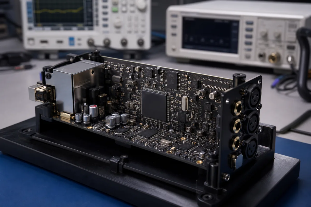
Digital Audio Signal Processor Module in a manufacturing environment
Representative product image. Confirm appearance and specifications with the manufacturer.

Product Specifications

Technical details and manufacturing context for Digital Audio Signal Processor Module

Definition
A digital audio signal processor module is an IC, system-on-chip, packaged module or populated board that performs programmable or fixed digital operations on audio sample streams. The implementation may be digital-only or include codecs, analogue front ends, memory, clocks, power regulation and connectors; ADCs and DACs are not inherent to every audio DSP. I2S/TDM commonly carry audio data while SPI/I2C commonly configure devices, but exact roles and timing are model-specific. Sampling rate, word length, channel count, processing latency/capacity, supply and power are digital-path properties; SNR and THD+N require a defined analogue signal path and measurement setup. Package/board size, temperature and environmental protection depend on the exact product boundary. The listed ranges are unverified comparison prompts, not one coherent module specification. Select against an exact data sheet, hardware/firmware revision, clocking, algorithm load, audio path, PCB and test conditions.
Working Principle
Digital audio samples enter through a defined serial, memory or network interface, are synchronized to one or more clock domains, processed by arithmetic cores and moved through buffers, mixers, filters or other algorithms before output. If analogue conversion is included, converter reference, analogue supply, input/output stage, load, reconstruction/anti-alias filtering and clock jitter become part of the measured path. Real-time performance depends on sample rate, channels, word format, instruction and memory bandwidth, routing, block size, firmware and clock plan. Power, latency, SNR, THD+N and stability must therefore be measured for the exact signal path and configuration.
Common Materials
Silicon semiconductor, FR-4 PCB substrate, Copper alloy contacts
Technical Parameters
ParameterTypical rangeNotes & selection driver
Sampling RateRequired44.1–192 kHzMaximum audio sampling frequency
Bit DepthRequired16–32 bitsAudio resolution in bits
Power ConsumptionRequired0.5–2.5 mWUnverified category prompt; state IC or module boundary, supply, clock, channels, algorithm load and test mode
Operating TemperatureRequired-40–85 °CTemperature range for reliable operation
Outline SizeRequired7×7–15×15 mmTwo-dimensional outline prompt; height, tolerances and IC/package or board boundary require an exact drawing
Interface TypeRequiredI2S, TDM, SPI, I2CPossible audio-data and control interfaces; exact roles, electrical levels, timing and supported modes require device evidence
Signal-to-Noise Ratio≥100 dBUnverified prompt; specify signal path, weighting, bandwidth, level, gain, load and test configuration
Total Harmonic Distortion + Noise≤0.005 %Unverified prompt; specify signal path, frequency, amplitude, bandwidth, weighting, gain, load and test configuration
Supply Voltage1.8–3.3 VCore and I/O voltage ranges
Operating Humidity10–90 % RHNon-condensing
Ingress ProtectionEnclosure-dependentOnly a declared enclosure or complete assembly has an IP code; not an intrinsic DSP IC or exposed-connector rating
Weight5–20 gDepends on package and heatsink

Ranges are indicative industry figures for RFQ preparation, not a supplier commitment. Confirm every value and standard with the legal manufacturer before ordering.

Components / BOM

Industry Taxonomies & Aliases

Commonly used trade names and technical identifiers for Digital Audio Signal Processor Module.

Industrial Ecosystem & Supply Chain Structure

Complementary Systems
Downstream Applications
Specialized Tooling

Application Fit & Sizing Matrix

Operational Limits
audio: Define analogue/digital paths, channels, sample rates, word/frame format, SNR/THD+N/dynamic-range conditions and latency.
compute: Define algorithms, instruction/accelerator needs, memory, block size, firmware tools and worst-case real-time load.
boundary: Identify bare IC/SoC, packaged module, evaluation board or production assembly and whether converters, memory, clocks and power are included.
interfaces: Map audio-data versus control ports, electrical levels, clock master/slave, routing, boot and external codec/amplifier connections.
environment: Set exact supply/thermal design, package/PCB drawing, assembly qualification, EMC and enclosure-level IP only where applicable.
Sizing Data Required
  • Start with channel/routing and end-to-end latency budget
  • Calculate worst-case processing and memory load for all enabled algorithms
  • Verify clock trees, sample-rate conversion and buffer/overrun behaviour
  • Measure exact analogue path and load if converters are included
  • Separate IC/package limits from final-board and enclosure claims

Reliability & Engineering Risk Analysis

Failure Mode & Root Cause
Audio dropout, corruption or unstable latency
Cause: Clock-domain, buffer, DMA/memory, firmware scheduling or processing load exceeds the configured real-time margin.
Noise or distortion misses the target
Cause: Converter/path conditions, gain, reference/supply noise, PCB return path, clock jitter, load or measurement setup differs from assumptions.
Module overheats or resets
Cause: Power was estimated at another clock, supply, channel count, algorithm load or product boundary.
Maintenance Indicators
  • Buffer under/overrun, clock unlock, sample slip, mute/reset or rising error count
  • Measured noise, distortion, frequency response or channel balance changes from the qualified baseline
  • Abnormal rail current, temperature, throttling or repeated boot/configuration failure
Engineering Tips
  • Instrument worst-case processing, memory and latency under the production firmware.
  • Measure the complete audio path with stated conditions and calibrated equipment.
  • Validate supply sequencing, clocks, thermal margin, connectors and enclosure on the final assembly.

Indicative industry ranges for design and RFQ preparation. Confirm the exact figures and applicable standard with the manufacturer before specifying.

Compliance & Manufacturing Standards

Applicable Standards
IEC 60529 classifies protection provided by a declared enclosure for electrical equipment. It does not give a bare DSP IC, PCB or exposed connector an inherent IP54–IP65 rating. ISO/IEC 14496-3 concerns coded representation of audio information and cannot establish that a module implements every codec or meets its electrical/audio performance. Audio performance or listening-safety standards apply only to their stated equipment, path, method and edition; they do not create universal SNR, THD+N, frequency-response or output limits for a generic DSP module. EMC and safety conformity normally applies to the complete equipment or declared subassembly under applicable product standards.

Quoted from the published standard.

Manufacturing Precision
  • No universal ±0.5 dB SNR tolerance, ±0.1 dB response, 5.5/6.0 V transient, 125 °C junction, 2.0/2.5 Vrms input, 5.3 V TVS or fixed attenuator range is asserted.
Quality Inspection
  • Confirm exact product boundary, part/board revision, interfaces, firmware, package/outline and environmental evidence.
  • Measure latency, processing margin, SNR, THD+N, response and crosstalk on defined paths and conditions.
  • Verify power, clocks, thermal design, EMC/safety and any enclosure IP on the final assembly.

Manufacturers of Digital Audio Signal Processor Module

1 company lists this product among what they make. Company figures are quoted from each company's own website; every card states where the relationship came from.

Shenzhen FHB Audio Technology Co., Ltd.
Shenzhen, Guangdong, CN
Listed on the company's own website · profile compiled by CNFX from public sources
Listed there as: “Dsp Digital Sound Processor”
View source page ↗ fhbavtecaudio.com · checked 2026-09-03

Manufacturer listings support early research and capability understanding. They are not certification, ranking, or transaction guarantees.

Share this page
Technical documentation
Request current drawings, revision history, and a signed specification sheet.
Manufacturing capability
Verify equipment lists, process limits, capacity, and representative production evidence.
Inspection readiness
Confirm test methods, calibrated equipment, sampling plans, and traceable reports.
Supplier transparency
Check the legal entity, factory address, ownership, certifications, and direct contacts.

CNFX does not score or rank suppliers. Buyers must verify all claims and documents with the legal manufacturer before ordering.

Frequently Asked Questions

Does every audio DSP module include an ADC and DAC?

No. Many devices are digital-only processors and use external converters; others integrate one or more converters. Verify the exact block diagram, pin functions and analogue path.

Can the page SNR and THD+N values be compared without test conditions?

No. Identify the measured input-to-output path, sample rate, bandwidth and weighting, signal level/frequency, gain, load, supply, clock and filter configuration. Digital-only DSPs may not have an intrinsic analogue SNR or THD+N.

Do I2S, TDM, SPI and I2C all carry the same audio stream?

No. I2S/TDM commonly transport sample data while SPI/I2C often provide control, although device roles vary. Verify electrical levels, master/slave role, word/frame format, clocks, channel slots and supported modes.

Does a DSP IC or exposed connector have IP54–IP65 by default?

No. IEC 60529 classifies protection provided by a declared enclosure. An IP code must identify the complete enclosure or assembly boundary and evidence; it is not intrinsic to a bare IC, board or exposed connector.

Data Basis

Editorial classification, named public sources where available, and source-reviewed manufacturer records.

Preliminary Technical Classification
This page supports structured research, RFQ preparation, and supplier evaluation. It does not replace buyer-led supplier qualification, standards review, or technical approval.
Buyer enquiry

Request manufacturing insight for Digital Audio Signal Processor Module

Ask for use case, specification boundaries, supplier type, and RFQ preparation information for this product.

Where it goes
Straight to the CNFX editorial desk, and to the manufacturer if this product is linked to a claimed profile. Nothing is broadcast to a supplier list.
Your details stay here
We do not sell or rent enquiry data, and we do not add you to a mailing list. Used only to answer this request.
No commission, no middleman
CNFX is a directory. We take no cut of any order and never negotiate on a supplier's behalf.
What we don't claim
A listing is not an endorsement. Qualify every supplier and verify every figure yourself before ordering.

Your business information is used only to process this request.

Thank you! Your message has been sent. We'll respond within 1–3 business days.
Sorry, we couldn't send your message. Please try again, or email us at [email protected].

Need to Manufacture Digital Audio Signal Processor Module?

Compare manufacturer profiles with relevant product and process capability.

Previous Product
Automated Surface Mount Technology (SMT) Pick-and-Place Machine
Last Product
Get QuotesChat