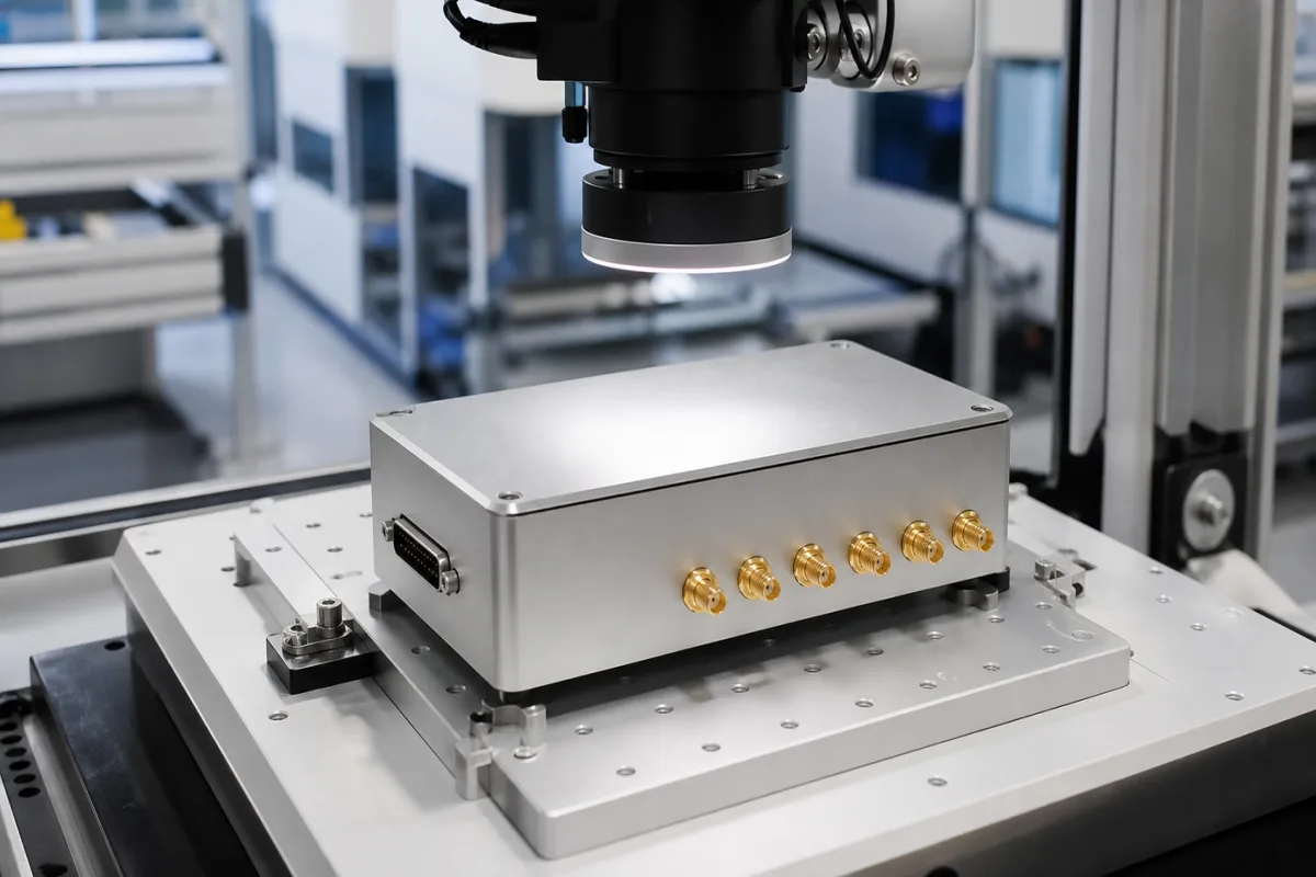
Digital-to-analog converter module (multichannel analog output module for PLC, remote I/O and test systems)
Analog output modules built around DACs · 0–10 V, ±10 V and 4–20 mA channels for PLC terminals, remote I/O and test systems, resolution, update rate, load, isolation and what the outputs hold when communication stops
Here the digital-to-analog converter is bought as a finished module: a terminal, card or box that takes values from a controller or test computer and drives two or more analog channels to valves, drives, setpoint inputs or a device under test. The converter IC inside is not the purchase. Settle the signal type and range per channel, how fast and how many channels must update together, what each output must drive, and what the outputs do if the controller or bus stops.
Multichannel analog output modules containing DACs: EtherCAT and fieldbus output terminals, I/O system output modules and test-system voltage output modules with 0–10 V, ±10 V or 4–20 mA channels. DAC chips themselves are covered on the DAC (digital-to-analog converter IC) page; input modules on the Analog input module for PLC, remote I/O and data acquisition page; function and arbitrary waveform generators on the Arbitrary waveform and function generators and Signal generator (function and arbitrary waveform generator) pages; audio converters and DSP boards on the Digital audio signal processor module page.
CNFX editorial research · Sources checked October 12, 2026 · 4 sources
Signal type, channel count, resolution and update rate
The four modules below show how far apart output modules sit even when they look alike on a datasheet line. Beckhoff states that the EL4104 "generate signals in the range between 0 and 10 V" with a resolution of 16 bits; its technical data gives "16 bit (incl. sign)" and an output rate of "max. 4 ksps". [1] The EL4024 "generates signals in the range between 4 and 20 mA" at 12 bits, with a conversion time of "~ 250 µs". [2] WAGO's 750-559 "generates standard 0–10 V signals" at 12 bits. [3] NI describes the NI-9264 as "a simultaneously updating analog output module" with 16 channels of -10 V to 10 V at 16 bits and 25 kS/s/ch, and says "Each channel has its own digital-to-analog converter." [4]
Editorial calculation from the stated ranges: a 0–10 V span split into 2^12 = 4,096 steps gives about 2.44 mV per step at 12 bits; split into 2^16 = 65,536 steps it gives about 0.15 mV. Beckhoff's "incl. sign" qualifier on the EL4104 means the 16 bits include a sign bit, so ask the maker how many steps are usable across 0…10 V before relying on the 0.15 mV figure. [1][3]
Voltage outputs are rated for a minimum load or a maximum current. Beckhoff gives the EL4104 load as "> 5 kΩ (short-circuit proof)". [1] NI lists a maximum current drive of 4 mA for the NI-9264. [4] The EL4024's current outputs are fed differently: "The output stages are powered by the 24 V supply." [2]
Editorial calculation: at 10 V, a 5 kΩ load draws 2 mA, and a 4 mA drive limit at 10 V corresponds to a load of 2.5 kΩ. List the input impedance of every valve amplifier, drive setpoint input or test input the module will drive, including cable and any parallel instruments, and check it against these figures. [1][4]
03
Ground and isolation
All three makers describe isolation between the bus side and the outputs, with the channels sharing a ground. The EL4104 is "electrically isolated" at 500 V between E-bus and signal voltage, and "The output channels of the EtherCAT Terminal have a common ground potential." [1] On the EL4024 the "Ground potential for the output channels of the EtherCAT Terminal is common with the 24 V DC supply." [2] WAGO says "The module's output channels have a common ground potential" and that the internal system supply powers the module. [3] NI lists 250 Vrms bank isolation for the spring-terminal versions of the NI-9264 and 60 VDC channel-to-earth-ground isolation for the D-Sub versions. [4]
Isolation on NI-9264 depends on the connector version ordered; name the part number, not just the model, when isolation matters. [4]
04
Holding or ramping outputs when communication stops
An output module keeps driving its last value, a set value, or nothing, depending on how its watchdog is set. Beckhoff lists "Watchdog parameterizable" for the EL4104 and, for the EL4024, "Optional watchdog: user-specific output value with ramp". [1][2]
The product pages do not say what the WAGO 750-559 or NI-9264 outputs do on loss of communication; ask for it in writing, along with the default setting as shipped. [3][4]
For each channel, write down the safe value on loss of communication (hold, zero, a set value, or a ramp to it) and confirm the module can be set to it.
05
Analog output module order details
Paste it into your enquiry below or into an email to a maker, then replace every bracket.
Channels: [number; 0–10 V / ±10 V / 4–20 mA per channel]
Resolution: [bits; usable steps]
Update: [rate per channel; simultaneous or not]
Load: [input impedance or current per channel]
Isolation: [bus to output; channel to channel; earth]
Bus or platform: [EtherCAT, fieldbus, I/O system, test chassis]
Loss of communication: [hold, set value, ramp]
Connection: [spring terminal, D-Sub, coaxial]
Quantity: [modules]
Explore company information and manufacturing capabilities, then discuss the scope of your project with a relevant supplier.
Share this page
Compiled and source-reviewed by the CNFX editorial team.
Each manufacturer above links to the page on that company's own website where the product is listed, with the date we checked it. How we source and review
· Page last updated 13 October 2026
Buyer questions
Is this the DAC chip or a module?
A module: a terminal, card or box with multiple finished analog output channels. The converter ICs alone are on the DAC (digital-to-analog converter IC) page. [1][4]
Can a 4–20 mA module run from the bus supply alone?
Beckhoff's EL4024 output stages are powered by the 24 V supply, so plan a 24 V feed for it. [2]
Do the channels update at the same time?
NI describes the NI-9264 as simultaneously updating with a DAC on each channel; for other modules ask the maker. [4]
What happens to the outputs if the bus fails?
It depends on the watchdog. Beckhoff's EL4024 offers an optional user-specific output value with ramp; ask other makers for the behaviour in writing. [2]
Sources and what still needs a direct check
Sources checked 2026-10-12. Beckhoff and WAGO publish product data for their analog output terminals and modules; NI publishes the NI-9264 product page with its specification table.