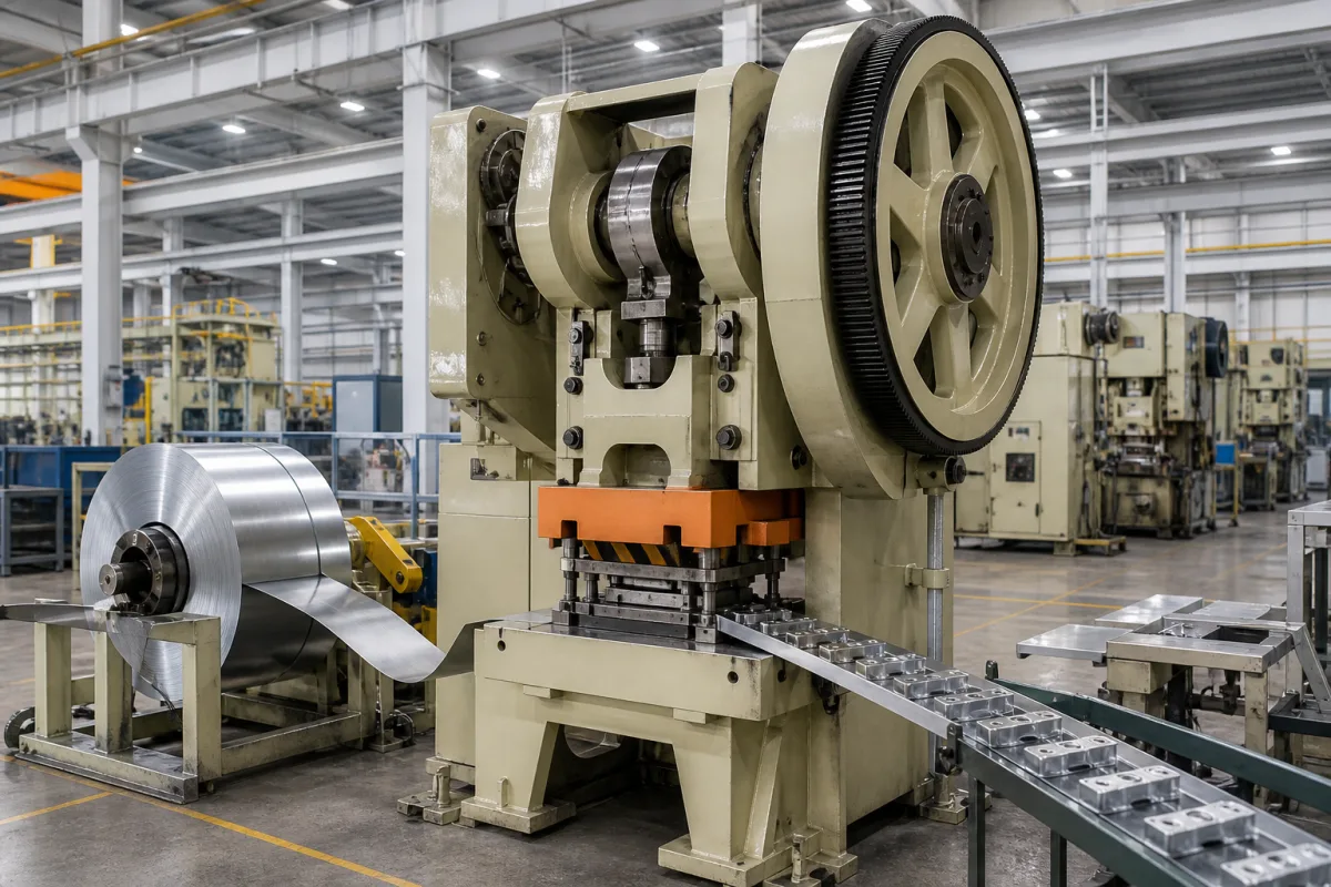
Crank and link presses · Rated tonnage point and tonnage curve, energy per stroke, clutch and brake safeguarding
A mechanical stamping press drives its slide through a flywheel, clutch and crank or link mechanism, so it delivers high stroke rates for blanking, forming and progressive-die work but reaches its full force only near the bottom of the stroke. Ask three things first: at what height above bottom dead centre its tonnage is rated and what the tonnage curve looks like above that, how much energy it delivers per stroke at the speeds you will run, and how the clutch, brake and point-of-operation guarding meet the safety rules that apply to you.
Flywheel-driven mechanical (crank, eccentric, link and knuckle) stamping presses with C or straight-side frames. Hydraulic presses, press brakes, servo-driven presses' motion programming, and dies and feeders are outside this page.
CNFX editorial research · Sources checked October 11, 2026 · 5 sources
Read the rated tonnage point and the tonnage curve
Writing for FormingWorld, press engineer Eren Billur explains that mechanical presses apply their rated tonnage at a certain point before bottom dead centre (BDC), and that the rated tonnage point, stroke and drive type (crank, link-motion or knuckle-joint) determine the tonnage curve. In his comparison of crank presses with 400 mm stroke, an 800 t press rated at 12 mm had more available force than a 1,000 t press rated at 6 mm at every point until about 8 mm before BDC, and in a bracket case study only the 800 t, 12 mm press could form the part although peak die force was 548 t. [1]
Billur adds that the energy a die needs is the area under its force-stroke curve, and that in a flywheel press reducing speed reduces energy per stroke sharply; when energy runs short the press may have to run single stroke, so the maximum clutch engagements per minute also matter. [1]
JDM's BSY series data, for example, gives the BSY300 S as 300 t rated 7 mm above BDC with a 250 mm stroke, 20–35 strokes per minute and 550 mm die height, and the H version as 300 t at 3 mm with a 170 mm stroke and 30–50 strokes per minute. [3]
Editorial calculation, simplified crank geometry that ignores connecting-rod length, with constant crank torque: for the BSY300 S (crank radius 125 mm, rated 300 t at 7 mm), available force falls to about 208 t at 15 mm, 152 t at 30 mm and 116 t at 60 mm above BDC. Ask the builder for the actual tonnage curve, because link and knuckle drives and real rod ratios change it. [3][1]
Give the supplier the parts and dies to be run, peak die force and the stroke position where forming starts, die energy per stroke, strokes per minute, bed and slide area, shut height and slide adjustment, stroke length, off-centre loading, feeding and automation, guarding method (light curtain, two-hand control, fixed guard), the safety standard that applies, supply voltage and foundation limits.
02
Check clutch, brake and safety distance
OSHA's mechanical power press rule, 29 CFR 1910.217, requires full-revolution clutch presses to have a single-stroke mechanism and two-hand trip systems with an antirepeat feature, and part-revolution clutch presses to release the clutch and apply the brake when the engaging means is removed, with a selector for Off, Inch, Single Stroke and Continuous. [2]
For two-hand controls and presence-sensing devices the minimum safety distance is Ds = 63 in/s × Ts, where 63 in/s is the hand-speed constant and Ts is the stopping time measured at about 90° of crankshaft rotation. Where operators feed or remove parts by hand in the point of operation, a control system and brake monitor are required; the brake monitor must automatically prevent the next stroke if stopping time or braking distance deteriorates beyond what the safety distance allows. Presence-sensing device initiation (PSDI) is not permitted on full-revolution presses. [2]
Editorial calculation: a press with a measured stopping time of 0.20 s needs a minimum safety distance of 63 × 0.20 = 12.6 in, about 320 mm, for a light curtain or two-hand control. [2] Editorial note: OSHA applies in the United States; ask the supplier which press safety standard the machine is built and certified to for your market.
03
Plan examination and guard checks where UK rules apply
OSHA's rule above sets how a press must be built and guarded in the United States. In Great Britain, the Provision and Use of Work Equipment Regulations 1998 add a recurring examination and inspection regime for power presses that the buyer must be able to carry out on the machine supplied. Regulation 32 requires every power press, with its guards and protection devices examined in position, to be thoroughly examined at least every 12 months where it has fixed guards only, and at least every 6 months in other cases, as well as before first use after installation or assembly at a new site and after exceptional circumstances that could affect safety. [4][2]
Regulation 33 adds checks within each working period. A power press must not be used after the fourth hour of a working period (a day's or night's work, or a shift) unless every guard and protection device has been inspected and tested in position by a person appointed in writing by the employer, who is competent or is training under the immediate supervision of a competent person. The same inspection is needed after setting, re-setting or adjusting the tools if the guards or protection devices were altered or disturbed. The signed certificate must identify each guard, device and press, state the date and time, and state that every guard and protection device is in position and effective. [5]
Editorial calculation: on a press guarded with a light curtain (not fixed guards only), the 6-month interval means at least 2 thorough examinations a year, and on a two-shift operation regulation 33 means at least 2 signed guard inspections a day, plus one after each tool change that disturbs the guarding. Ask the press supplier for guard and protection-device designs that can be inspected and tested quickly in position, and for the stopping-time measurement method the examiner will use. [4][5]
Suppliers linked to this page list mechanical stamping presses; each card links to the page reviewed.
Listings range from C-frame open-back crank presses to straight-side double-crank presses and high-speed presses; ask each for the tonnage curve, energy-per-stroke data and stopping-time measurements.
05
Trace the press components
This is a functional reference built from the sources cited; it is not one maker's design.
Fill the specification fields with values for your dies
A mechanical press quotation needs values for your dies and parts. The table explains each field, gives published values where a reviewed source states them, and says what to obtain from the supplier.
Field
What it means and published values
Ask the supplier for
Tonnage Capacity (tons)
Rated at a height above BDC; e.g. 300 t at 7 mm. [3]
Explore company information and manufacturing capabilities, then discuss the scope of your project with a relevant supplier.
Share this page
Compiled and source-reviewed by the CNFX editorial team.
Published product pages show what a company offers, not tested performance. Confirm the legal seller, factory and scope for your order. How we source and review
· Page last updated 13 October 2026
Buyer questions
What is the rated tonnage point of a mechanical press?
The height above bottom dead centre at which the press delivers its nominal force; above it the available force falls along the tonnage curve. [1]
Can a smaller mechanical press form a part a bigger one cannot?
Yes; Billur shows an 800 t press rated at 12 mm forming a bracket that a 1,000 t press rated at 6 mm could not. [1]
How is the safety distance for a mechanical press calculated?
OSHA 1910.217 uses Ds = 63 in/s × Ts, the stopping time measured at about 90° of crank rotation. [2]
How often must a power press be thoroughly examined in the UK?
PUWER 1998 regulation 32 requires at least every 12 months for presses with fixed guards only and at least every 6 months otherwise; regulation 33 requires guard checks before the end of the fourth hour of each working period. [4][5]
Sources and what still needs a direct check
Sources checked 2026-10-11. OSHA 29 CFR 1910.217 is a US regulation; PUWER 1998 regulations 32 and 33 are UK law for power presses in England, Wales and Scotland; Billur is a press and forming engineer writing on FormingWorld; JDM's data describe its own presses.