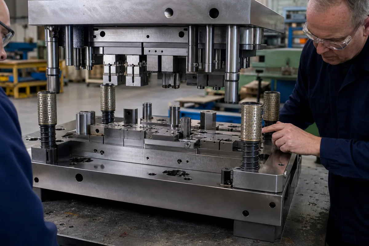
Die set with ball-bearing guide pillars: die shoes, preloaded ball cages and bushings that align a press tool
The guided frame a press tool is built into · upper and lower die shoes, guide pillars, bushings and preloaded ball cages: balls about 0.0005 in larger than the gap, a cage that travels half the stroke, and plain bushings honed after assembly
The punches, dies and pilots of a stamping tool are mounted on two thick plates, the die shoes. The upper shoe goes on the press ram, the lower on the bolster, and between them guide pillars running in bushings keep the two halves aligned through every stroke, whatever the press slide itself does. This page is about that frame: whether the pillars run in plain bushings or preloaded ball cages, how the cage moves and wears, and what the shoes are made from.
Die sets for press tools: upper and lower die shoes with guide pillars (guide pins, leader pins), plain or ball-bearing bushings, ball and roller cages, sold as catalogue or special sets for stamping, blanking and forming tools. The progressive and transfer tools that are built into a die set are covered on the Progressive die set page, press brake punches and dies on the V-die set page, and open-die forging presses on the Hydraulic open-die forging press page; extrusion die holders are outside this page.
CNFX editorial research · Sources checked October 13, 2026 · 3 sources
Balls slightly larger than the gap: how a preloaded ball cage holds the two die shoes in line
Lempco Industries' patent US4648727A describes a punch press die set whose upper and lower shoes are kept in vertical alignment by two preloaded ball-bearing assemblies, each a bushing in the lower shoe, a pin in the upper shoe and a ball retainer between them. The balls exceed the radial space between pin and bushing slightly, "e.g. 0.0005 in.", so they are compressed and roll under an interference fit. [1]
Editorial calculation: 0.0005 in is 12.7 µm; 150 m/min is 2.5 m/s.
Agathon describes its preloaded pillar guides as backlash-free and free of stick-slip when correctly designed, with a cylindrical bore that is cheaper and more precise to make than the seats for profiled rail guides and needs no preload adjustment at installation. [2]
Guide feature
Published figure or statement
Ball interference
Ball diameter exceeds the radial gap by e.g. 0.0005 in [1]
Origin
Compression-loaded ball-bearing die sets go back to Conner's US 2,422,774 of 1947 [1]
Deflection at maximum load
From a few micrometres up to approx. 0.01 mm, depending on guide size and rolling elements (Agathon pillar guides) [2]
100Cr6 bearing steel; stainless alloys as an alternative (Agathon) [2]
Rolling elements
Balls, which also allow two-axis movement, or rollers (Agathon) [2]
State the guide type wanted (ball or plain), pillar diameter and number, the cutting clearance the tool needs, and the press speed in strokes per minute and stroke length.
02
The cage travels half the stroke: sizing cage and bushing length, and spreading ball wear
Under preload the retainer moves in the same direction as the pin but only half as far, so Lempco indexes it to travel into the bushing a distance equal to half the full stroke; if it is not indexed when the balls are first loaded, it can be driven into the press bed, bolster or upper shoe. [1] Agathon states the same kinematics and adds a limit: the cage should stay preloaded over at least 50 % of its length at any stroke position, so cage and bushing length set the maximum stroke. [2]
Editorial calculation: for a 100 mm stroke the cage moves 50 mm; if, for illustration, a cage is 120 mm long, at least 60 mm of it must remain inside the preloaded zone of the bushing at both ends of the stroke under Agathon's rule.
Balls running in the same track wear lines into pin and bushing. Lempco lists earlier remedies, helical ball patterns so no two balls share a track and cages free to rotate when the pin is withdrawn, and adds a key running in a slot along the pin that lets the cage be turned and reciprocate while staying indexed. [1] Dieco's retainers use a helical pattern so each ball has its own linear path, with a set screw keying the retainer to a slot in the guide pin. [3]
Give the maximum stroke and shut height, whether the tool is separated from the press with pins withdrawn, and how ball tracking on pins will be checked at maintenance.
03
Die shoes and plain-bushing sets: A-36 or aluminium plates, stress relief and bushings honed after assembly
Dieco's catalogue die sets show the other choices a buyer makes. [3]
Editorial calculation: 23 in is 584 mm.
Editorial note: honing plain bushings after they are pressed into the shoe removes any distortion the press fit causes; ball-bearing components instead rely on matched grinding, which is why Dieco sells them as interchangeable parts.
Explore company information and manufacturing capabilities, then discuss the scope of your project with a relevant supplier.
Share this page
Compiled and source-reviewed by the CNFX editorial team.
Each manufacturer above links to the page on that company's own website where the product is listed, with the date we checked it. How we source and review
· Page last updated 13 October 2026
Buyer questions
How much preload does a ball-bearing die set guide have?
Lempco's US4648727A gives an example of balls about 0.0005 in (12.7 µm) larger than the radial gap between pin and bushing, so they are slightly compressed. [1]
How far does the ball cage move in a die set?
Half the stroke of the pin; Agathon adds that the cage should stay preloaded over at least 50 % of its length in every position. [1][2]
Why are plain bushings honed after assembly?
Dieco supplies plain bushings with a nominal allowance on the bore so they can be honed after they are pressed into the die shoe. [3]
Sources and what still needs a direct check
Sources checked 2026-10-13. Preload and cage kinematics come from Lempco Industries' US4648727A; cage length, deflection and speed from Agathon's description of its pillar guides; shoe material and bushing preparation from Dieco's die set catalogue page.