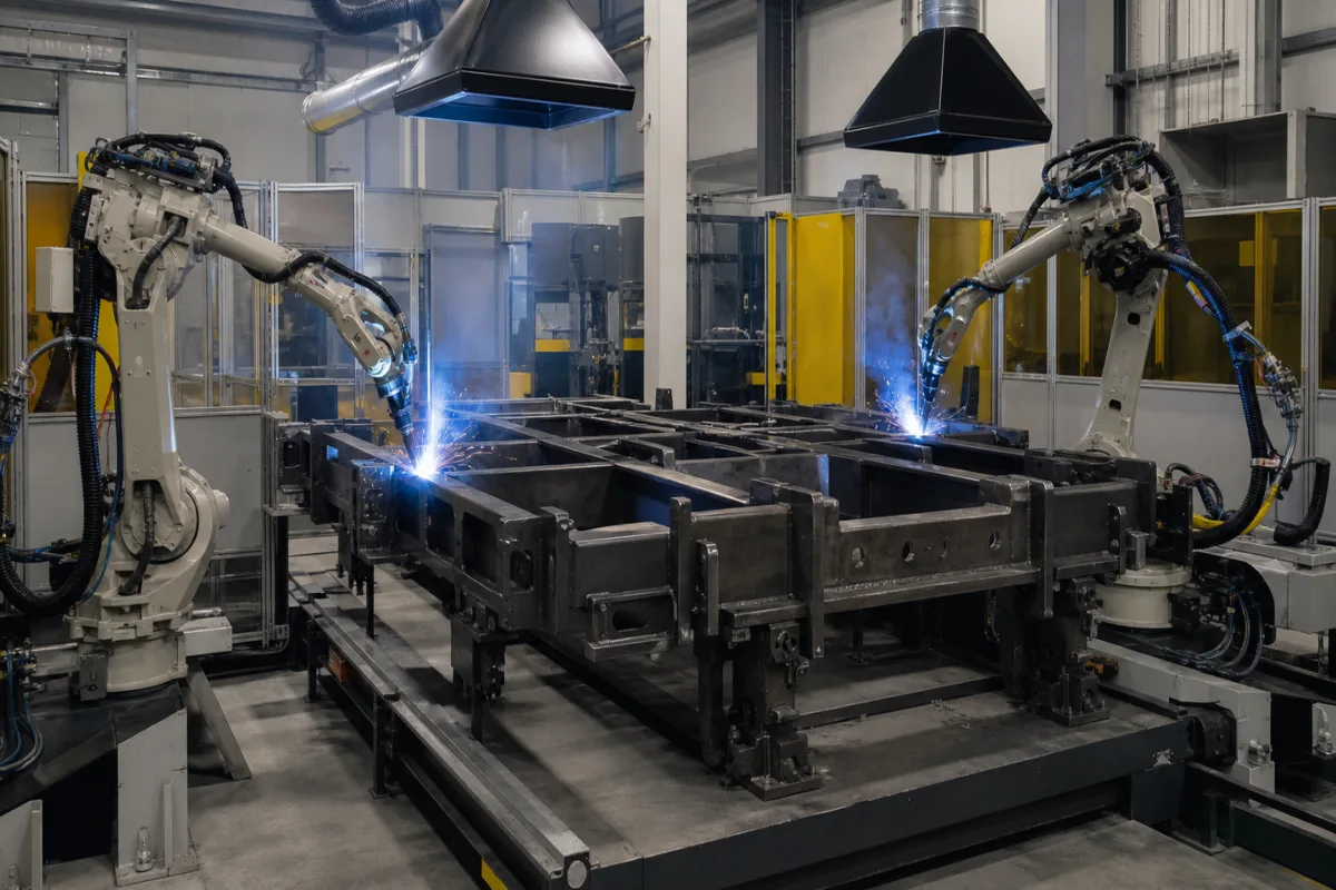
Trailer frame welding station with wire touch sensing and through-arc seam tracking: robots that find and follow fillet joints on cut and fitted frame members
Trailer and frame fabrication · robot welding stations that locate each joint on cut and tacked steel with the welding wire, then follow the fillet through the arc while welding
Trailer frame members are cut, fitted and clamped in a fixture before the robots weld them, and each part can sit away from where the robot program expects it, with a gap at a fillet that varies along its length. A welding station for this work needs two corrections: finding where each joint actually is before the arc starts, and keeping the torch on the joint while it welds. This page covers the two methods that use the welding wire and the arc themselves for that, without a camera or laser on the torch.
Robotic MAG welding stations for trailer, semi-trailer and similar steel frame sub-assemblies in which the robots correct their programs to the real part: wire touch sensing to locate joints, edges and gaps before welding, and through-arc seam tracking with a weave during welding, with the torch, wire and part conditions those methods depend on. Complete trailer frame welding cells, gantries, headstock-tailstock positioners and frame handling are covered on the Trailer frame welding robot page. Laser and camera seam-tracking heads are covered on the Sensor-equipped robot laser welding head page; torch cable routing on the Robotic arm for welding page; wire supply from drum to feeder on the Wire feed system page; fume capture on the Welding fume extraction systems page. Switchgear frame welding on a reconfigurable clamping bed is covered on the Frame welding station for switchgear and enclosure frames page, spot welding of aluminium car bodies on the Robotic welding station for aluminium car bodies page, and robots that hold body parts in place of a fixture on the Frame positioning robot with a locating gripper page.
CNFX editorial research · Sources checked October 13, 2026 · 5 sources
Touching the joint with the energised wire before the arc: edge, height and gap on cut frame members
In wire touch sensing the robot moves the wire against the part at a low sensor voltage and records where contact happens. Fronius describes its WireSense version as using reversing wire movements to measure height, so that edges and gaps are found without a camera on the torch. [1]
Fronius explains the sequence: a very low sensor voltage is applied to the wire, the wire touches the component and makes a short circuit at a current too low to weld, the wire is lifted again, and the power source turns the wire position at the instant of contact into a height signal that the robot controller combines with its own position data. [1] When the measured values differ from the stored ones, the robot corrects its coordinate system or tool centre point, which is what compensates for component and clamping tolerances. [1] The magazine article lists detection of sheet thicknesses between 0.5 and 20 mm in steel, stainless steel and aluminium, and edge detection on sheet as thin as 0.5 mm. [1]
For a trailer frame, the gap function matters as much as the edge. Because the wire records the overall height of two overlapping members, the station can calculate the gap between them and call up a welding job stored for that gap size, slowing travel or changing power; where the gap is too large for that, Fronius points to its Cold Metal Transfer process. [1] Fronius also gives its reasons for not using a camera on the torch: the camera restricts the view of the seam at some torch angles, takes up space needed to reach the part, and needs maintenance and calibration in welding conditions. [1]
Cause of a failed or false touch
What Yaskawa's support note says to do
Mill scale, dirt or oil on the parts
Recognise it as a cause of no-touch faults; the same contamination also causes weld problems [3]
Tap water in a water-cooled torch
Use distilled or deionised, very low-conductivity coolant; tap water lets algae form, causing false touches through the coolant and blocking the torch water ports [3]
Ball, burn-back or glass on the wire tip
Fit a wire cutter so each touch starts from a clean-cut wire [3]
Wire cast (a tight curl, near the end of a spool or from the drive rolls)
Install a wire straightener in the feed system [3]
If the frame members are supplied with mill scale or oil on the surfaces the wire will touch, ask the station builder which surfaces each search uses, whether the torch has a wire brake and cutter, and how the coolant is specified.
02
Following the fillet while welding: through-arc tracking needs a weave, a fillet and a changing stick-out
Yaskawa's ComArc function shows the conditions a through-arc tracker sets on the joint and on the weld program.
Editorial calculation from these figures: the minimum 2.5 mm amplitude is half the waveform, so the torch sweeps at least 5 mm across the joint; at the 2.5 Hz default each weave cycle takes 0.4 s. [2][4] Tracking only runs between the ComArc start and end instructions, which replace the normal weave-on and weave-off instructions, and setting it up takes a phase-compensation test without the top plate followed by a sensing test on the real joint. [2]
Yaskawa's weaving note adds a point for cycle-time estimates: the programmed speed is the speed of the tool centre point along the path without weaving, so the torch moves faster overall than that figure and the travel speed may need to be lowered as amplitude and frequency rise. [4] The note also states that the weave motion is only generated correctly if the programmed tool data is accurate. [4] On a trailer frame, welds that are neither fillets nor deep unfilled grooves fall outside ComArc's stated conditions, so they have to be located by touch sensing before welding or by another sensor. [2]
At least 8 inches long [2]; editorial conversion: about 203 mm
Weave amplitude input (Weld Builder)
0.1 to 99.9 mm, measured as half the waveform height [4]
Weave frequency input (Weld Builder)
0.1 to 5 Hz, default 2.5 Hz; amplitude and frequency may not exceed 30.0 mm and 4.0 Hz at the same time [4]
List which welds on the frame are fillets long enough to track, which are grooves or butt joints, and whether the weld procedure allows a weave of at least 2.5 mm amplitude on each of them.
03
From manual bays to a robot cell at a heavy-trailer builder: 40 to 60 % less manufacturing time
Scott's account of the robot welding system it installed at Drake Trailers, an Australian builder of low loaders and steerable platform trailers, gives before-and-after figures for trailer components.
Before automation, Drake welded components by hand and labourers rotated heavy components manually; the company reported that components lacked uniformity for fitment and machining. [5] After installation, Scott reports manufacturing time reduced by 40 to 60 % depending on the component and machining time reduced by 15 to 20 %, and one operator working the three-station cell where the plant previously ran three or four welding bays on two shifts. [5] The headline of the same account states a 64 % reduction in cycle time, a figure outside the 40 to 60 % range given in the body text; ask which components either figure refers to before using it for a business case. [5]
The Drake cell used one robot on a linear track serving two positioner stations and a long table. [5] That layout question, robot carrier and positioners for frames, is the subject of the Trailer frame welding robot page; the sensing methods above apply whichever carrier is chosen.
When comparing quotations, ask each supplier for the sensing method per weld, the search time added to each cycle, and the reduction in fit-up rework or machining they expect, stated per component.
04
Data for a sensing-equipped trailer frame welding station
Paste it into your enquiry below or into an email to a maker, then replace every bracket.
Parts: [frame sub-assemblies; materials; thickness range; surface condition: scale, primer, oil]
Fit-up: [cutting method; expected position deviation; gap range at fillets]
Welds: [list by joint type: fillet, groove, butt; lengths; leg sizes]
Touch sensing: [searches per part; wire cutter; wire brake; torch coolant]
Arc tracking: [welds to track; weave amplitude and frequency allowed by the procedure]
Gap handling: [jobs per gap size; low-heat process for large gaps]
Robots: [number per station; reach; existing power sources]
Explore company information and manufacturing capabilities, then discuss the scope of your project with a relevant supplier.
Share this page
Compiled and source-reviewed by the CNFX editorial team.
Each manufacturer above links to the page on that company's own website where the product is listed, with the date we checked it. How we source and review
· Page last updated 13 October 2026
Buyer questions
How thick can the material be for wire touch sensing?
Fronius lists detection of sheet thicknesses between 0.5 and 20 mm for its WireSense system, in steel, stainless steel and aluminium. [1]
Why does a touch-sensing robot report no touch?
Yaskawa's support note lists mill scale, dirty or oily parts, a balled or glassed wire tip, wire moving in the liner without a wire brake, wire cast and, for false touches, tap water in a water-cooled torch. [3]
Can through-arc seam tracking follow a butt joint?
Yaskawa states that ComArc needs a fillet joint, or a deep groove that is not completely filled, because the stick-out must change across the weave; fully filled grooves are not recommended. [2]
What weave does through-arc tracking need?
ComArc requires weaving with an amplitude of at least 2.5 mm; Yaskawa's Weld Builder accepts 0.1 to 5 Hz, default 2.5 Hz. [2][4]
How much time did robot welding save at a trailer builder?
Scott reports a 40 to 60 % reduction in manufacturing time and a 15 to 20 % reduction in machining time at Drake Trailers; its headline gives 64 %. [5]
Sources and what still needs a direct check
Sources checked 2026-10-13. Fronius explains wire touch sensing and its thickness range; three Yaskawa Motoman support articles give the conditions for through-arc tracking, the weave limits and the causes of touch faults; Scott's case study gives before-and-after figures from a heavy-trailer builder.