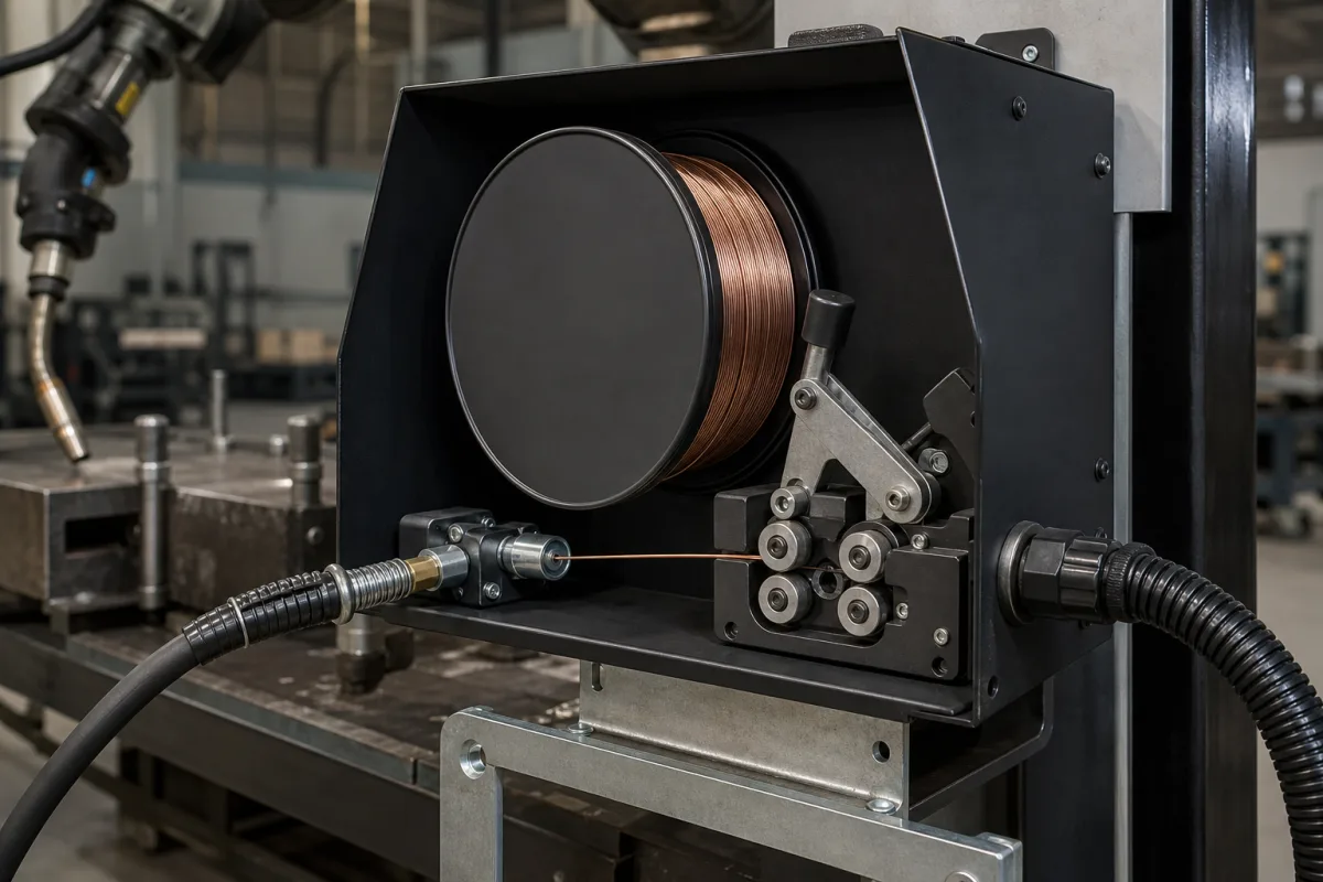
MIG/MAG wire feeders · Bench, dual or portable suitcase type, wire type and diameter, feed speed range, welding current rating and duty cycle, spool size, drive rolls, input power and control
A wire feeder pushes welding wire from a spool through the gun cable to the MIG/MAG torch at a set, steady speed while the power source supplies the arc. Settle three things before choosing one: the feeder type and welding current and duty it must carry, the wire material, diameter, speed range and spool it must handle, and the drive rolls, input power, controls and enclosure for where it will work.
Wire feeders for semi-automatic MIG/MAG (GMAW) and flux-cored (FCAW) welding — bench, dual-wire, boom-mounted and portable suitcase feeders, and the drive roll kits used in them. Welding power sources, torches and guns, robotic wire-feed systems integrated into robots and submerged-arc heads are outside this page; welding power sources and welding torches have their own pages.
CNFX editorial research · Sources checked October 11, 2026 · 4 sources
Pick the feeder type, current rating and duty cycle
Miller's wire feeder range covers bench and dual feeders, boom-mounted SwingArc feeders, PipeWorx feeders, ArcReach and SuitCase portable feeders and the XR-AlumaFeed suitcase feeder for aluminium. [1] Its Intellx Basic Dual is a dual feeder for manufacturing, heavy equipment and railcar work with a 600 A at 113 VDC, 60% duty cycle input-circuit welding rating, 50 VDC input power, 18 in (457 mm) 60 lb (27 kg) spools and a 77 lb (about 35 kg) net weight, 17.8 × 34.7 in footprint. [2]
Its SuitCase 12RC is a portable feeder with remote voltage control for jobs within 100 ft of the power source, rated 425 A at 60% duty, powered at 24 VAC, 10 A, 50/60 Hz, taking 12 in, 45 lb spools in an impact-resistant, flame-retardant case that protects components and wire from moisture, dust and contaminants, at 31 lb net weight. [3]
Editorial note: size the feeder's current rating and duty cycle to the welding procedure, not only the power source, and choose a portable case for site work where the feeder is moved and dragged. [2][3]
Give the supplier the process (MIG/MAG, flux-cored, pulsed), wire material and diameters, feed speed range, welding current and duty cycle, number of wires (single or dual), spool or drum size, power source model and control interface, input power, cable lengths, mounting (bench, boom, portable), enclosure and environment, and quantity.
02
Match wire type and diameter, feed speed and drive rolls
The Intellx Basic Dual handles 0.6–2.0 mm (0.023–0.078 in) solid steel wire at 1.3–19.8 m/min (50–780 IPM). [2] The SuitCase 12RC handles 0.023–0.052 in solid steel and 0.030–5/64 in flux-cored wire at 50–700 IPM, for steel, stainless and specialty metals. [3]
Miller lists V-groove drive roll kits for solid wire, U-groove kits for aluminium and soft wire to minimise deformation, and V-knurl kits for flux-cored wire, each sized to wire diameter (for example 0.023, 0.030, 0.035, 0.045 and 0.047 in). [3]
Editorial calculation: feed speed and wire diameter set the metal fed — a 1.2 mm wire has a 1.13 mm² cross-section, so at 10 m/min it feeds about 11,300 mm³/min, or about 89 g/min (5.3 kg/h) of steel at 7.85 g/cm³ before spatter and other losses. 50 IPM × 0.0254 = 1.27 m/min, matching Miller's 1.3 m/min minimum. [2]
03
Compare a second maker's dual feeder data
Fronius publishes technical data for its WF 25i Dual, a feeder with two wire spools for changing filler metal without re-threading. It lists a 2 × 4-roller drive, 0.8–1.6 mm (0.02–0.06 in) wire and a wire feed speed of 1–25 m/min (39.37–984.25 ipm). The two versions differ by spool holder, as the table shows. [4]
Set against Miller's Intellx Basic Dual (0.6–2.0 mm wire, 1.3–19.8 m/min, 18 in / 27 kg spools), the Fronius unit lists a narrower wire range but a higher top feed speed, and offers the larger 450 mm spool holder at the cost of a lower IP rating (IP20 against IP23 for the 300 mm version). Check the enclosure rating against where the feeder will stand. [4][2]
Editorial calculation: at the Fronius maximum of 25 m/min, a 1.2 mm wire (1.131 mm²) feeds about 28,300 mm³/min, or about 222 g/min (13.3 kg/h) of steel at 7.85 g/cm³ before spatter and other losses — 2.5 times the 10 m/min example above. [4]
The companies in the manufacturer list below show this product on their own websites. Confirm the legal seller, factory and scope for your order.
Ask each supplier for the spec sheet with wire diameters by type, feed speed range, current rating and duty cycle, spool capacity, input power and the power sources and guns it is compatible with. [2][3]
05
Trace what each part controls
This is a functional reference built from the sources cited; it is not one maker's specification.
Fill the specification fields with values for your welding
A wire feeder quotation needs values for your welding. The table explains each field, gives published values where a reviewed source states them, and says what to obtain from the supplier.
Explore company information and manufacturing capabilities, then discuss the scope of your project with a relevant supplier.
Share this page
Compiled and source-reviewed by the CNFX editorial team.
Published product pages show what a company offers, not tested performance. Confirm the legal seller, factory and scope for your order. How we source and review
· Page last updated 13 October 2026
Buyer questions
What feed speed range does an industrial wire feeder cover?
Miller's Intellx Basic Dual lists 1.3–19.8 m/min (50–780 IPM) for 0.6–2.0 mm solid steel wire. [2]
Which drive rolls should I use for flux-cored or aluminium wire?
Miller lists V-knurl rolls for flux-cored wire, U-groove for aluminium and soft wire and V-groove for solid wire. [3]
What current rating do wire feeders carry?
Miller lists 600 A at 60% duty for the Intellx Basic Dual and 425 A at 60% for the SuitCase 12RC. [2][3]
What is a suitcase wire feeder?
A portable feeder in a protective case; Miller's SuitCase 12RC adds remote voltage control within 100 ft of the power source. [3]
How fast can a production dual wire feeder feed wire?
Fronius lists 1–25 m/min (39.37–984.25 ipm) for its WF 25i Dual with 0.8–1.6 mm wire and two spools of up to 300 mm or 450 mm diameter. [4]
Sources and what still needs a direct check
Sources checked 2026-10-11. Miller's wire feeder range and product specification pages and Fronius's WF 25i Dual technical data are used to show what a wire feeder specification covers; values for your order must come from the supplier's current spec sheet.