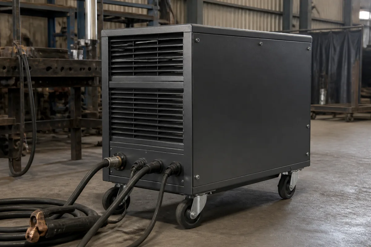
Arc welding power sources · Open-circuit voltage limits, rated conditions for temperature and altitude, enclosure of input and output terminals, supply conductors and grounding
A welding power source converts mains (or engine) power into the controlled current and voltage that sustain a welding arc. Settle three things before ordering: the process, rated output current, duty cycle and output range the work needs; the open-circuit voltage and shock-protection features for where it will be used; and the input supply, enclosure, service conditions and interfaces for the installation or robot cell.
Arc welding power sources (transformer, rectifier and inverter types, AC and DC) for manual and automated welding and cutting. Welding torches, wire feeders, positioners, fixtures and resistance or capacitor-discharge welders are outside this page; torches, positioners, fixtures and capacitor-discharge welders have their own pages.
CNFX editorial research · Sources checked October 12, 2026 · 4 sources
Check open-circuit voltage and rated service conditions
US OSHA rule 29 CFR 1910.254 limits open-circuit voltage to 80 V for AC machines used for manual arc welding and cutting, 100 V for AC machines used for automatic (machine or mechanised) welding and cutting, and 100 V for DC machines used manually or automatically. Where special processes need higher open-circuit voltage, the operator must be protected from accidental contact by insulation or other means; for AC welding in wet conditions or warm surroundings it recommends automatic controls that reduce no-load voltage. [1]
The rule requires standard arc welding machines to carry their rated load with rated temperature rises where cooling air does not exceed 40 °C (104 °F) and altitude does not exceed 3,300 ft (1,005.8 m), and to be suitable for atmospheres with welding gases, dust and arc light. It lists unusual service conditions that call for specially designed machines, including corrosive fumes, steam or humidity, oil vapour, flammable gases, vibration or shock, excessive dust, weather and seacoast or shipboard exposure. It refers to NEMA EW-1 and the UL safety standard for transformer-type machines as design references. [1]
Editorial note: if the machine will run in a hotter shop, at altitude or outdoors, state those conditions in the enquiry so the supplier confirms the rating, or derating, for them. [1]
A maker's rating data show how these fields appear on a real machine. Jasic's sheet for its MIG 350 multi-process inverter (order code JM-352S) lists AC 400 V 50/60 Hz input, 15 kVA input power and 13.2 A effective input current; 15–36 V output voltage, 50–350 A for MIG and 20–350 A for MMA; 350 A at 40% duty cycle at 40 °C; 65 V no-load voltage; 85% efficiency and power factor 0.93; wire speed 1–16 m/min; IP21S protection and class F insulation; 1,020 × 505 × 1,460 mm and 104 kg. [4]
Editorial calculation: the sheet's 65 V no-load voltage is below the 100 V limit that 1910.254 sets for DC machines; and at 85% efficiency, every 10 kW of arc output draws about 11.8 kW from the supply, so size the feeder from the rated input current on the plate, not from the arc power. [4][1]
Give the supplier the process (SMAW, GMAW, GTAW, FCAW, SAW, cutting), rated output current and duty cycle at your ambient, output voltage range, AC or DC and polarity, open-circuit voltage and any voltage-reduction device, input voltage, phases and frequency, rated primary current, enclosure rating, ambient temperature, altitude and environment, robot or automation interface, cooling, and quantity.
02
Plan supply conductors, terminals and grounding
1910.254 requires control apparatus to be enclosed except for operating handles; input power terminals, tap changers and live input parts to be completely enclosed and reachable only with tools; and welding-lead terminals to be protected from accidental contact by dead-front receptacles, recessed openings with hinged covers or heavy insulation. Portable control devices carried by the operator must not connect to AC circuits above 120 V, and exposed metal parts on such devices above 50 V must be grounded. [1]
For installation, it requires a disconnect switch or controller at or near each machine, supply conductors for an individual machine rated at no less than the machine's rated primary current, and grounding of the machine frame (except engine-driven machines). It warns that with more than one welder on one structure, no-load voltages between electrode holders can reach 2 times normal for DC or 1, 1.41, 1.73 or 2 times normal for AC, and requires DC machines to share polarity and AC machines to share phase and instantaneous polarity. [1]
Editorial note: size the feeder from the rated primary current on the nameplate, and for a bank of machines on one structure plan polarity and phase connection before installation. [1]
On construction sites, 29 CFR 1926.351 adds requirements around the power source. Welding cables must be completely insulated and flexible, able to carry the maximum current of the work, taking the duty cycle into account. They must be free of repairs or splices for at least 10 ft from the electrode-holder end. A ground return cable must carry at least the specified maximum output of the unit it serves, or the total of all units when one cable serves more than one. Pipelines carrying gases or flammable liquids, and electrical conduits, must not be used as ground returns. Machine frames must be grounded through a third wire or a separate wire grounded at the source. Operators must open the power supply switch when leaving the work for an appreciable time or moving the machine. [2]
Ventilation belongs in the same installation plan. Under 29 CFR 1910.252(c)(2), mechanical ventilation of at least 2,000 cu ft (57 m³) per minute per welder is required for general welding in a space under 10,000 cu ft (284 m³) per welder, in a room with a ceiling under 16 ft (5 m), or in confined or obstructed spaces, unless local exhaust hoods and booths or approved airline respirators are provided. [3]
03
Find suppliers
The companies in the manufacturer list below show this product on their own websites. Confirm the legal seller, factory and scope for your order.
Ask any supplier for the rating plate data (rated output, duty cycle, open-circuit voltage, rated primary current) and the safety standard the machine is listed to. [1]
04
Trace what each part controls
This is a functional reference built from the sources cited; it is not one maker's specification.
Part
What it controls
Fix in the order
Power conversion stage
Output current and voltage; IGBT inverter in one machine. [4]
Fill the specification fields with values for your welding
A welding power source quotation needs values for your welding. The table explains each field, gives published limits where a reviewed source states them, and says what to obtain from the supplier.
Explore company information and manufacturing capabilities, then discuss the scope of your project with a relevant supplier.
Share this page
Compiled and source-reviewed by the CNFX editorial team.
Published regulations set limits, not a supplier's tested output. Confirm the legal seller, maker and listing for your order. How we source and review
· Page last updated 13 October 2026
Buyer questions
What is the maximum open-circuit voltage for a welding machine?
OSHA 1910.254 limits it to 80 V for manual AC welding and 100 V for automatic AC and for DC welding. [1]
At what ambient are welding machines rated?
OSHA says standard machines carry rated load with cooling air up to 40 °C and altitude up to 3,300 ft. [1]
How are supply conductors for a welder sized?
For an individual machine, at no less than its rated primary current. [1]
What happens when more than one welder works on one structure?
OSHA warns no-load voltage between holders can reach up to 2 times normal and requires matched polarity and phase. [1]
How large must a welding ground return cable be?
29 CFR 1926.351 requires it to carry at least the specified maximum output of the unit it serves, or the total of all units it serves. [2]
When is mechanical ventilation required for welding?
29 CFR 1910.252 requires at least 2,000 cu ft/min per welder in spaces under 10,000 cu ft per welder, rooms under 16 ft high, or obstructed or confined spaces, unless local exhaust or approved respirators are used. [3]
What does a 350 A inverter welding power source rate plate show?
One maker's 400 V machine gives 350 A at 40% duty cycle at 40 °C, 65 V no-load voltage, 13.2 A effective input current, 85% efficiency and power factor 0.93. [4]
Sources and what still needs a direct check
Sources checked 2026-10-12. US OSHA 29 CFR 1910.254 sets arc welding equipment requirements. 29 CFR 1926.351 and 1910.252 add US requirements for cables, grounding and ventilation.