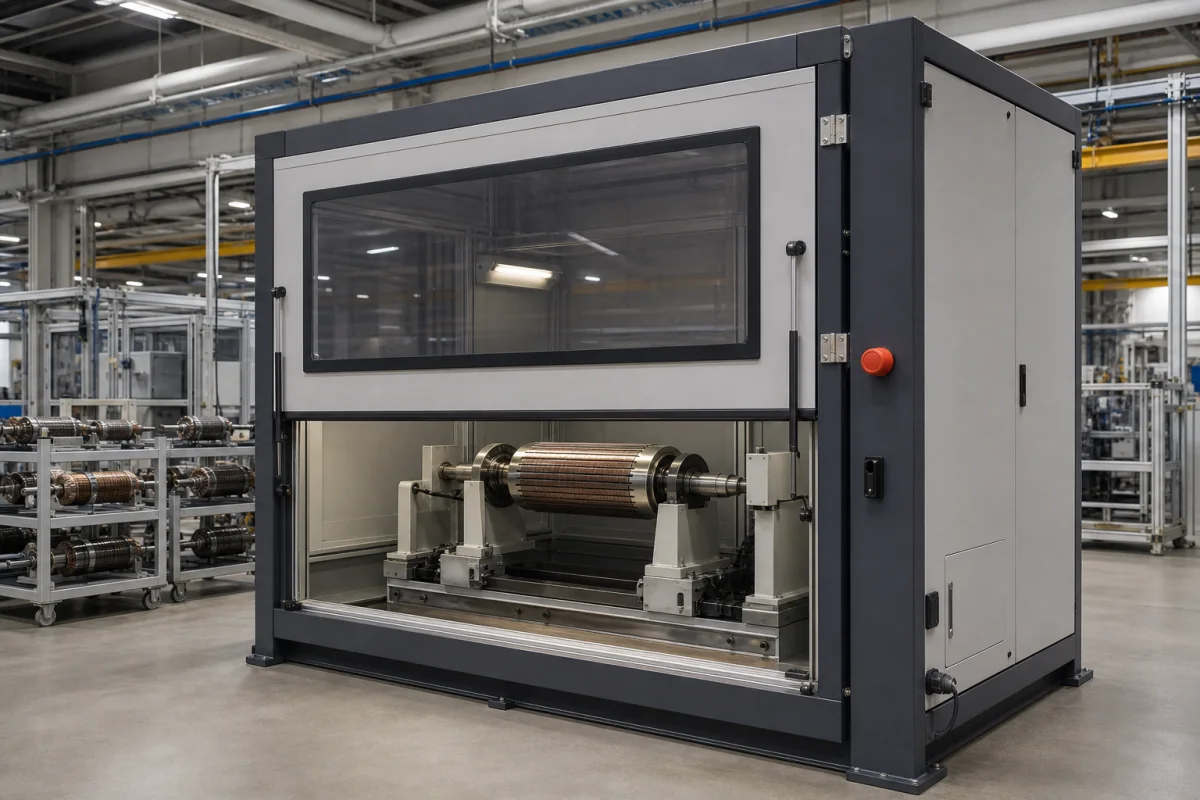
Safety enclosure for rotor balancing machines: ISO 21940-23 protection classes
Balancing machine enclosures · ISO 21940-23 protection classes A to D, guard-free criteria, polycarbonate vision panel mounting
A balancing machine safety enclosure is the guard, hood or housing around the measuring station of a rotor balancing machine that keeps operators away from the spinning rotor and drive and stops particles, correction weights or rotor fragments from leaving the work zone, built with a polycarbonate vision panel and interlocked doors. Ask three things first: which ISO 21940-23 protection class the rotors, speeds and correction method call for, how the vision panel is mounted and protected, and how the enclosure is interlocked for production and set-up modes.
Guards, hoods and enclosures for the measuring station of rotor balancing machines, rated by ISO 21940-23 protection class, including their vision panels and interlocks. The balancing machines themselves, with their tolerances, correction stations and verification, are covered on the Electric motor rotor balancing machine page; perimeter fencing for robot cells and lines is covered on the Machine and robot cell safety guarding page. EMC and electrical test safety boxes are outside this page.
CNFX editorial research · Sources checked October 12, 2026 · 3 sources
Find the protection class from what can leave the rotor
ISO 21940-23:2012 judges the danger from a particle or part flying off the rotor by three criteria: area-specific energy, where the part's energy is concentrated on its smallest area and must not penetrate; absolute energy, where it loads the whole structure of the protective device, which must not disintegrate; and impulse, which must not overturn the protective device or move it too far. [1] Its Table 2 then sets four classes:
The standard notes that classes A and B can be combined, for example when a rotor is dangerous to touch and only small particles of limited energy can be ejected; the 2012 edition replaced ISO 7475 and deleted the former protection class 0. [1] Editorial calculation: a 0.4 kg fragment leaving at 100 m/s carries ½ × 0.4 × 100² = 2,000 J (N·m), the class C absolute-energy limit, with an impulse of only 40 kg·m/s. Since energy equals impulse² ÷ (2 × mass), the 200 kg·m/s impulse limit corresponds to 2,000 J at a mass of 10 kg, so for parts heavier than 10 kg the impulse limit is reached first.
Minimum protection to prevent contact with rotating parts; no particles released [1]
C
Yes
Area-specific energy up to about 340 mN·m/mm², absolute energy up to about 2,000 N·m, impulse up to about 200 kg·m/s [1]
D
Yes
Any of these values above the class C criteria [1]
Give the supplier the heaviest and largest rotor, maximum balancing speed and diameter, correction method (adding weights or removing material), what could detach (weights, blades, windings, the whole rotor), the protection class required, loading method (crane, robot, manual), and the interlock and mode requirements.
02
When the standard lets a balancing machine run without guards
ISO 21940-23 requires the work zone of a balancing machine to be guarded by barriers, fences, enclosures or covers, and allows guards to be omitted only when all six criteria apply: a smooth rotor surface with no entanglement risk; a correction method that cannot detach particles; a speed at which major rotor failure is not expected; the rotor prevented from lifting out of the bearings, or too small to cause damage if it does; drive torque so limited that the force needed to stop rotation is below 100 N at every relevant radius; and kinetic energy of rotor plus drive below 20 N·m at balancing speed. [1]
A guarded machine needs two modes: Mode 1, production, with the enclosure closed or protective devices active; and Mode 2, setting, with the enclosure open and interlocks suspended, provided only where the instructions define the application and operator skill, with reduced balancing speed named as a significant factor in reducing risk. [1]
03
Mount the polycarbonate vision panel so it stays in the frame
In tests by the German institute for occupational safety (BIA, now IFA) on polycarbonate vision panels up to 12 mm thick, struck by projectiles of 0.1 to 2.5 kg under the European machine-tool standards, clamped or adhesive joints let the panels absorb impacts best; bolted joints were less suitable because they prevent the panel deforming, and clamping profiles of the kind found on older machines proved unsuitable for higher impact energies. [2]
The same project found that with too little overlap between the panel and the surrounding frame the panel can be pushed out of its mounting whole; it set a minimum overlap of 12.5 to 37.5 mm depending on the energy and panel thickness, and warned that fully exploited panels can transmit impact forces of up to 90 kN to the structure. [2] An earlier BIA study found 8 mm polycarbonate roughly equal in impact resistance to 3 mm Fe P01 steel sheet, but with limited ageing stability that calls for additional panes on both sides to protect it from cooling lubricants. [3]
Editorial note: these tests were made for metal-cutting machine guards, not balancing machines; use them for how a panel is held, and take the energy to be resisted from the balancing machine's protection class.
04
Data for a balancing enclosure enquiry
Paste it into your enquiry below or into an email to a maker, then replace every bracket.
Rotors: [largest mass; diameter; length; type]
Speed: [maximum balancing speed]
Correction: [adding weights or removing material]
Class: [ISO 21940-23 A, B, C or D]
Vision panel: [size; thickness; mounting; protective panes]
Access: [doors; loading by crane or robot]
Interlocks: [guard locking; Mode 1 and Mode 2]
Explore company information and manufacturing capabilities, then discuss the scope of your project with a relevant supplier.
Share this page
Compiled and source-reviewed by the CNFX editorial team.
Each manufacturer above links to the page on that company's own website where the product is listed, with the date we checked it. How we source and review
· Page last updated 13 October 2026
Buyer questions
What are the class C limits in ISO 21940-23?
Area-specific energy up to about 340 mN·m/mm², absolute energy up to about 2,000 N·m and impulse up to about 200 kg·m/s; anything above is class D. [1]
Can a balancing machine run without an enclosure?
Only if all six ISO 21940-23 criteria apply, including stopping force below 100 N and rotor-plus-drive kinetic energy below 20 N·m. [1]
How should the vision panel be fixed?
BIA/IFA tests favour clamped or adhesive joints with 12.5–37.5 mm overlap over bolted joints. [2]
Sources and what still needs a direct check
Sources checked 2026-10-12. Protection classes and guard criteria come from the published preview of ISO 21940-23:2012 (hosted by iTeh); vision panel findings from the IFA project record BIA 6057 and the 2000 BIA study by Mewes and Trapp in the International Journal of Occupational Safety and Ergonomics. The full standard governs.